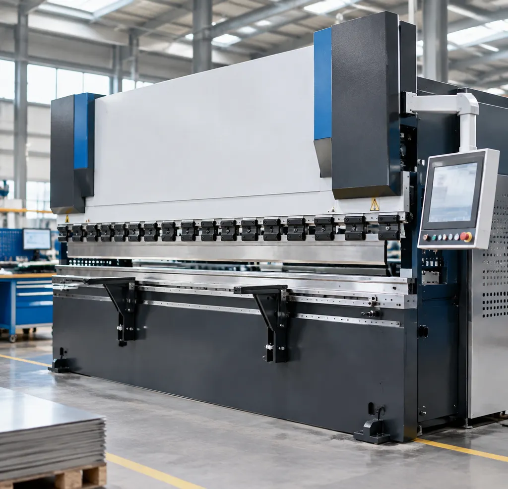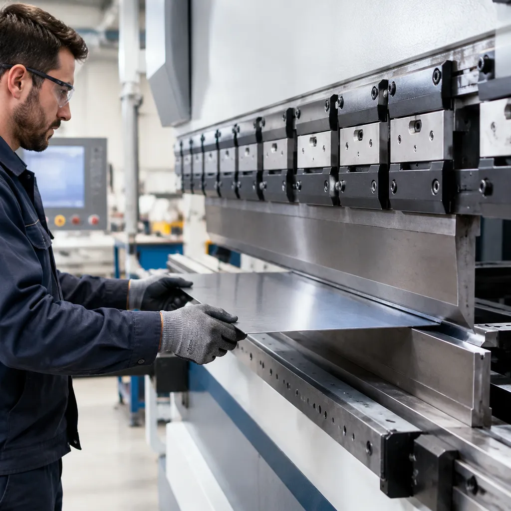
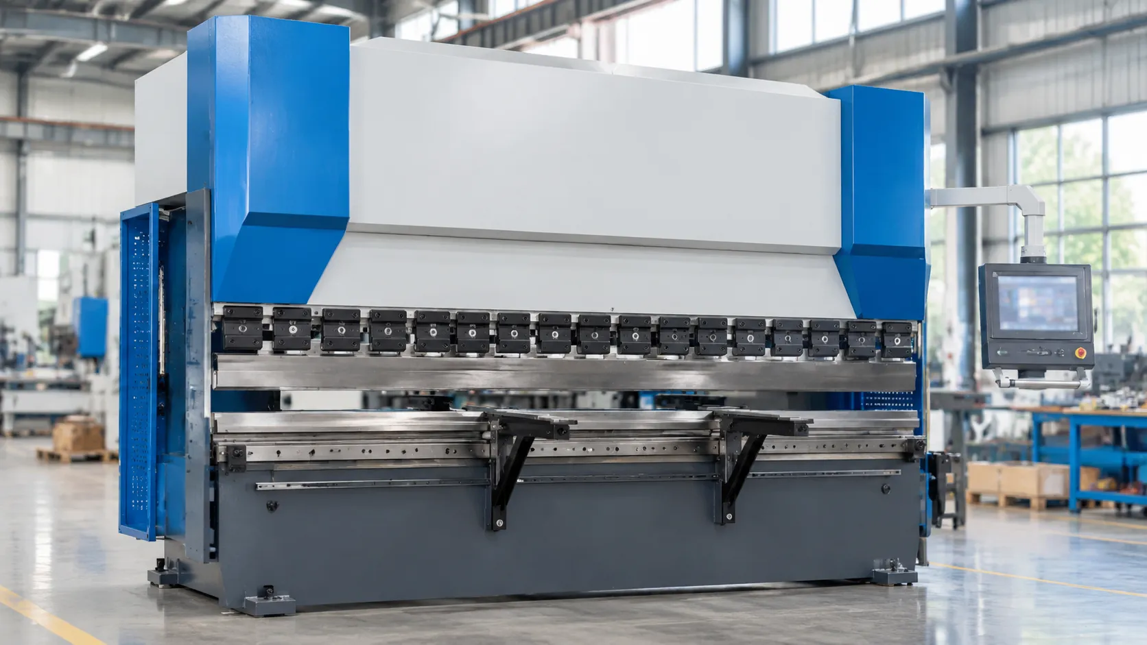
What Is an Electro-Hydraulic CNC Press Brake?
If you have spent any time running a metal fabrication shop, you know the frustration of uneven flange angles, wasted trial sheets, and constant manual shimming. An electro-hydraulic CNC press brake solves these exact workshop headaches by combining raw hydraulic force with precise digital synchronization.
At its core, what is an electro-hydraulic cnc press brake? It is an advanced sheet metal bending machine that uses computer-controlled proportional servo valves and independent hydraulic cylinders to drive and balance the upper beam (ram). Instead of relying on rigid mechanical links to keep the ram level, it continuously monitors and adjusts oil flow to both cylinders in real time.
How the Machine Functions
The operating process is fast, smooth, and automated:
-
- Digital Input: We input the sheet thickness, material type, and target angle directly into the machine interface.
- Synchronized Descent: The hydraulic power unit pumps high-pressure oil through dedicated proportional valves into the left and right cylinders.
- Precise Positioning: The ram descends under strict electronic control, pressing the punch into the die with exact depth control down to the micron.
- Dynamic Correction: If one side encounters more resistance, the system instantly modulates valve pressure to keep the tool perfectly parallel.
The Role of the CNC Controller in Modern Bending
In our daily operations, the CNC controller acts as the central brain of the bending cell. Modern controllers take the guesswork out of complex jobs:
-
- Automated Calculations: They instantly calculate the required tonnage, bend deductions, and backgauge positions.
- Angle Simulation: Operators can visually review 2D or 3D bend sequences before touching a single piece of sheet metal, eliminating tooling collisions.
- Process Repeatability: Once a bending program is stored, any operator can run the same job months later and hit identical tolerances.
How Electro-Hydraulic Systems Differ from Basic Setups
Traditional hydraulic machines rely on a physical torsion bar or manual mechanical depth stops inside the cylinders. While simple, these older designs lack adaptability.
-
- Basic Hydraulic Brakes: Both cylinders are mechanically tied together. They cannot make real-time corrections, they struggle with off-center bending, and wear on the mechanical links leads to angular taper across long parts.
- Electro-Hydraulic Servo Systems: Each cylinder operates independently via its own servo valve and closed-loop feedback. The machine actively compensates for pressure variations, frame deflection, and off-center loads, giving us consistent bend angles from the first part to the ten-thousandth.
Key Components of an Electro-Hydraulic Press Brake
To really understand what an electro-hydraulic CNC press brake is capable of, you have to look at the hardware driving the machine. In our shop, we treat these machines as integrated systems where high-speed electronics constantly balance high-pressure hydraulics.
Five core assemblies make this precision possible:
-
- CNC Controller System and Software: As the central brain, the controller runs 2D or 3D graphic software from industry standards like Delem, ESA, or Cybelec. It calculates bend allowances, monitors collision zones, and automatically determines the correct axis movements and pressure profiles before the punch even touches sheet metal.
- Proportional Electro-Hydraulic Servo Valves: Instead of basic on/off directional valves, these high-response proportional valves meter oil flow to the left and right cylinders separately with microsecond responsiveness. They provide continuous flow control to keep both sides synchronized down to microns.
- Dual Linear Optical Encoders (Y1 and Y2 Position Tracking): We mount high-resolution linear scales directly to independent C-frames on both machine sides. By reading real-time position directly from the ram rather than the main side housings, the system tracks the Y1 and Y2 axes without being distorted by bed deflection under load.
- Hydraulic Power Unit, Pump, and High-Pressure Cylinders: The power system pairs a quiet, high-efficiency motor-pump setup with rigid, heavy-duty hydraulic cylinders. Modern CNC hydraulic press brakes use optimized oil circuits that deliver instant pressure for clamping and bending while drastically cutting thermal buildup during long production shifts.
- Multi-Axis CNC Backgauge System: Repeatable bending demands rock-solid backgauging. Driven by AC servo motors and precision ballscrews, backgauges range from standard depth and height controls on a 3-axis CNC press brake to advanced 6-axis configurations (X1/X2, R1/R2, Z1/Z2) that reliably gauge tapered, asymmetric, or multi-station setups.
How the Closed-Loop Synchronization System Works
Every fabricator knows the nightmare of a twisted flange or an uneven angle across a long bend. In our shop, understanding what is an electro-hydraulic CNC press brake comes down to how it eliminates that headache through true closed-loop synchronization. Instead of forcing both ends of the ram together mechanically, the machine continuously monitors and balances the hydraulic cylinders independently.
Independent Y1 and Y2 Cylinder Monitoring
In an electro-hydraulic system, the ram does not move as a rigid, dumb beam. The left and right cylinders—designated as the Y1 and Y2 axes—operate on their own dedicated circuits:
-
- Separated Hydraulic Lines: Each cylinder receives hydraulic fluid through its own independent servo proportional valve.
- Direct Real-Time Tracking: High-precision optical linear encoders mounted on the side frames constantly measure the exact vertical position of each side of the ram, completely isolated from frame deflection under load.
- Zero Mechanical Twist: Unlike mechanical systems that fight torsion under unbalanced pressure, Y1 and Y2 run on pure electronic balance.
Real-Time Microsecond Valve Adjustments
The closed-loop mechanism is lightning fast. While the bend is taking place, the machine executes thousands of corrections per second:
-
- Position Sensing: The scales detect position shifts down to the micron.
- Instant Comparison: The CNC controller compares the actual positions of Y1 and Y2 against the target bend profile.
- Dynamic Response: If one side meets harder material or encounters structural resistance, the controller throttles or increases fluid flow via the proportional valves within milliseconds to keep both ends parallel.
Eliminating Angular Errors and Uneven Pressure
This constant adjustment prevents the angle deviations that ruin parts during long-bed production or multi-station setups. When bending parts paired with our overall plate forming solutions, maintaining consistent depth ensures every part fits downstream fixtures perfectly.
-
- Uniform Penetration: The punch penetrates the V-die at the exact same depth from tip to tail.
- Balanced Force Distribution: The system dynamically redistributes hydraulic tonnage without tilting the ram.
- Consistent Part Output: You get reliable 90-degree bends across 10-foot or 14-foot sheets without endless shimming or wasted test blanks.
Electro-Hydraulic vs Torsion Bar vs Pure Electric Press Brakes
When fabricators ask us what is an electro hydraulic CNC press brake compared to other workshop options, the conversation always comes down to drive mechanics, control precision, and operating costs. Here is how these three core bending technologies stack up on the shop floor.
Electro-Hydraulic vs Torsion Bar Synchronization
Traditional torsion bar press brakes connect both cylinders using a rigid mechanical steel bar to force synchronized movement. While simple, mechanical wear, uneven hydraulic resistance, and frame deflection quickly lead to angular discrepancies across longer bends. You cannot tilt the beam for taper bending, and off-center bending causes severe mechanical binding.
In contrast, an electro-hydraulic sync press brake eliminates the mechanical link entirely. We use independent hydraulic cylinders controlled by proportional servo valves and optical linear encoders (Y1 and Y2 axes). The CNC continuously monitors and corrects each cylinder independently in real time, giving you:
-
- True independent ram control with micro-level positioning accuracy.
- Effortless off-center bending without damaging the machine frame.
- Tapered and step-bending flexibility by running Y1 and Y2 at programmed offsets.
Electro-Hydraulic vs All-Electric Servo Systems
Comparing an electro-hydraulic unit to an all-electric press brake highlights a balance between raw bending force and clean operating speed. Advanced servo electric press brakes bypass hydraulic fluid completely, driving the ram via servo motors, belts, or direct-drive ball screws.
While a dedicated electric press brake with direct drive servo CNC offers unbeatable cycle speeds and zero hydraulic maintenance for thin sheet fabrication, electro-hydraulic setups remain the undisputed heavyweights. They deliver the continuous high tonnages, heavy-plate capacities, and stroke lengths that pure electric systems cannot match at practical manufacturing costs.
Technology Comparison: Tonnage, Precision, Speed, and Cost
| Feature | Torsion Bar Hydraulic | Electro-Hydraulic CNC | Pure Electric Servo |
|---|---|---|---|
| Tonnage Range | 30T – 500T+ | 40T – 2,000T+ (Heavy-duty capable) | Typically 30T – 150T (Limited high tonnage) |
| Positioning Accuracy | ±0.05 mm to ±0.1 mm | ±0.01 mm (Closed-loop feedback) | ±0.005 mm to ±0.01 mm |
| Approach & Return Speed | Moderate (Standard valves) | Fast (High-response proportional valves) | Ultra-fast (Instant servo motor response) |
| Off-Center Loading | Poor (Risk of mechanical jam) | Excellent (Dynamic Y1/Y2 auto-compensation) | Good (Within localized tonnage ratings) |
| Power Consumption | Constant pump idle draw | Optimized with inverter/servo hydraulics | Ultra-low (Power drawn only during bending) |
| Initial Investment | Lowest entry cost | Moderate to high (Best ROI for heavy jobs) | Higher upfront capital cost per ton |
Key Benefits of an Electro-Hydraulic CNC Press Brake
In our fabrication shop, scrap metal and rework eat profits faster than anything else. Switching to an electro-hydraulic system eliminates the daily headaches of inconsistent angles, endless test bends, and uneven parts.
When operators ask what an electro-hydraulic CNC press brake delivers over older machinery, the answer comes down to four major operational advantages:
1. Unmatched Bending Precision and Repeatability
Because the Y1 and Y2 cylinders operate under a closed-loop servo system with dedicated linear encoders, the ram tracks position dynamically in real time.
Target tolerance: ram positioning remains accurate within ±0.01 mm.
Consistency: The first bend matches the five-hundredth bend, even across varied sheet metal batches.
Complex geometry: Multi-bend profiles maintain exact tolerances without cumulative angle drift.
Investing in the best CNC press brake for precision metal forming ensures that your tight-tolerance parts pass quality control on the first pass every single time.
2. Safe Off-Center and Multi-Station Step Bending
Conventional torsion-bar brakes bind and suffer mechanical damage if you bend off-center. An electro-hydraulic CNC press brake handles unbalanced loads effortlessly:
Asymmetrical compensation: Proportional valves feed pressure independently to each side, preventing ram tilting.
Multi-stage setups: We can set up multiple tooling stations along the bed—such as punch-and-die sets for punching, hemming, and 90-degree bending—to complete a complex part in a single handling cycle without damaging the machine frame.
3. Automated Deflection Compensation (Crowning)
Long workpieces naturally deflect under high tonnage, causing the dreaded "canoe effect" where the center of the bend is wider than the ends. Modern electro-hydraulic units eliminate this through automated crowning:
| Crowning Type | Operation Principle | Key Advantage in Production |
|---|---|---|
| Mechanical Crowning | CNC-driven dual-wedge system moves along the lower beam. | High durability, precise wave contouring, and zero hydraulic drift over long hold times. |
| Hydraulic Crowning | Built-in hydraulic auxiliary cylinders apply counter-pressure under the bed. | Fast automatic adjustment directly matched to real-time bending force. |
The CNC controller calculates the exact tonnage, material tensile strength, and sheet thickness, automatically dialing in the right compensation profile before the punch touches the sheet.
4. Faster Setup Times and Reduced Scrap Rates
Manual test bends and shimming dies waste valuable operator hours. With intuitive CNC control and precise hydraulic positioning:
Bending programs, axis coordinates, and tooling profiles load instantly from the library.
Digital angle calculation reduces scrap down to near zero on initial runs.
Tooling changes and backgauge repositioning take seconds rather than minutes, maximizing machine uptime during high-mix, low-volume runs.
Industrial Applications and Best Use Cases
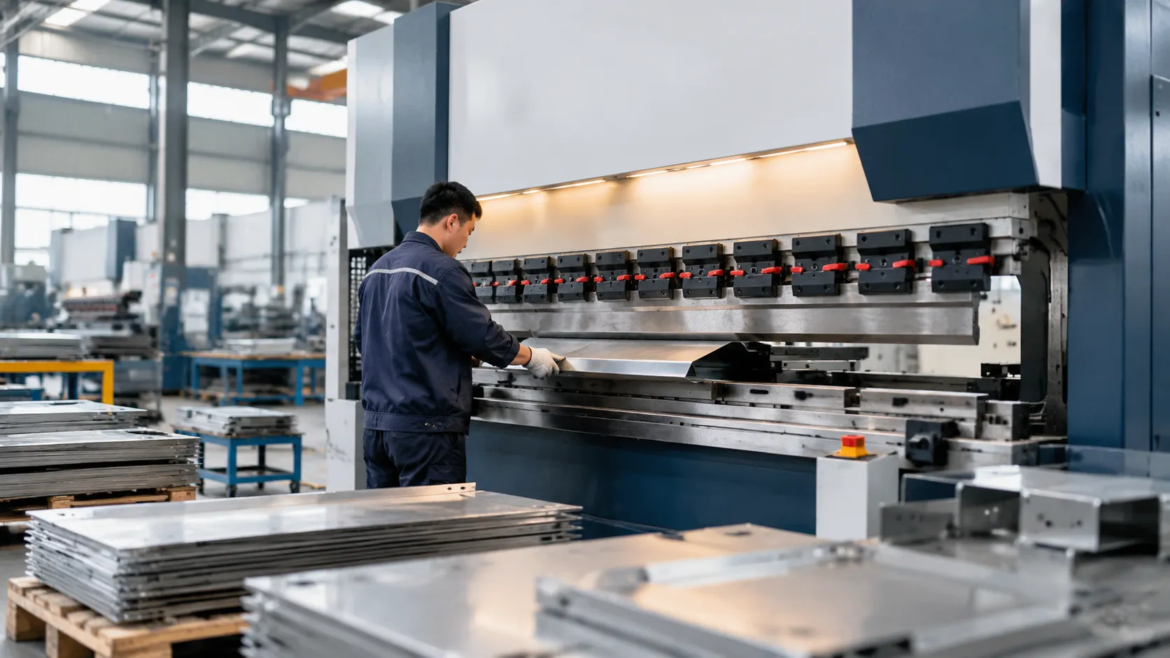
When fabricators ask us what an electro-hydraulic CNC press brake does best, the answer comes down to versatility under demanding shop conditions. Whether we are forming ultra-thick plate or running high-speed production on light-gauge parts, an electro-hydraulic CNC press brake delivers the tonnage control and axis synchronization needed across high-volume and high-tolerance industries.
Heavy Machinery and Structural Steel Manufacturing
Forming thick plate requires high tonnages, heavy-duty frames, and zero cylinder drift. In structural steel fabrication, crane manufacturing, and earthmoving equipment production, we rely on synchronized hydraulics to eliminate angle variations over long bend lines.
-
- Thick plate processing: Handles high-tensile structural grades without frame distortion.
- Long-span uniformity: Independent cylinder management keeps large channel and box sections straight from end to end.
- Heavy infrastructure: Built to meet rugged requirements in the construction and architecture industry.
Automotive, Railway, and Aerospace Sheet Metal Parts
Modern transportation manufacturing demands tight tolerances and repeatable results on exotic alloys, aluminum, and high-strength steels. We integrate these brakes into our high-precision sheet metal bending solutions to ensure every piece meets tight inspection standards without manual rework.
-
- Automotive chassis and brackets: High repeatability for multi-bend structural brackets and crash-resistant components.
- Rail car components: Long profile bending for side walls, roof ribs, and undercarriage supports.
- Aerospace panels: Micro-level depth control on high-grade aluminum and titanium alloys prevents material cracking and springback variance.
Precision Electrical Enclosures, Cabinets, and HVAC Ductwork
For thin-gauge sheet metal, setup speed and backgauge flexibility dictate profitability. Multiple bend flanges, narrow channels, and tight corners require seamless multi-axis backgauge movements and precise step-bending programs.
-
- Server racks and control cabinets: Tight radius control ensures clean, square corners for seamless assembly.
- HVAC ductwork and transitions: Fast ram speeds handle rapid cycling on galvanized sheet metal without surface marring.
- Appliance housings: Accurate flange lengths prevent assembly gaps and reduce scrap rates on pre-painted or polished surfaces.
How to Select the Right Electro-Hydraulic CNC Press Brake
When buyers ask us what is an electro-hydraulic CNC press brake best suited for in their facility, we look straight at four core technical parameters to ensure they get the exact capability they need without overspending.
1. Calculating Required Bending Tonnage and Working Length
Tonnage sizing dictates machine longevity and accuracy. Running a machine at 100% capacity on every bend wears down the hydraulic seals and structural frame rapidly.
-
- Material tensile strength: Stainless steel requires roughly 1.5 times the force of mild steel, while aluminum requires about half.
- V-die opening ratio: We typically apply an 8:1 rule (die opening = 8x material thickness) for standard air bending.
- Safety buffer: Always add a 20% tonnage safety margin over your maximum calculated load. If daily jobs involve heavy plate fabrication, stepping up to a rigid 300-ton CNC press brake prevents deflection issues across broad bed spans.
2. Choosing the Right CNC Press Brake Axis Configuration
The number of independently controlled axes determines setup speed, backgauge flexibility, and complex profiling ability:
-
- 3+1 or 4+1 Axes (Y1, Y2, X, R + V crowning): The standard workshop setup. Covers 80% of regular sheet metal jobs, managing bend depth, backgauge depth, gauge height, and automatic bed crowning.
- 6+1 Axes (Y1, Y2, X, R, Z1, Z2 + V): Ideal for shops switching frequently between different flange lengths and multi-station tooling setups across the bed.
- 8+1 Axes (adds X1, X2, R1, R2): Necessary for asymmetric, tapered, or irregular aerospace and industrial components where independent finger stop positions are critical.
3. Tooling Styles and Clamping Systems
Tool changeover time directly impacts hourly shop margins. Selecting the right interface depends on job frequency:
-
- European / Amada-Promecam Style: The most common worldwide standard. Cost-effective, readily available from third-party tooling suppliers, and ideal for standard manual or pneumatic quick-clamp setups.
- New Standard / Wila-Trumpf Style: Precision self-seating tooling loaded vertically. Excellent for high-mix operations where operators swap punches frequently without needing lateral slide-in space.
4. Evaluating Hydraulic Oil Cooling and Energy-Saving Servo Drives
Modern electro-hydraulic systems integrate dynamic motor control rather than conventional continuous-run motors:
-
- Servo-Hydraulic Drives: The pump motor only runs when the ram moves, cutting idle electrical power consumption by up to 50% and keeping hydraulic fluid significantly cooler.
- Cooling Systems: Air-cooled heat exchangers handle moderate ambient environments, while dedicated industrial oil chillers are required for multi-shift high-cycle factories operating in hot climates to prevent servo valve contamination and seal degradation.
Maintenance Best Practices for Maximum Uptime
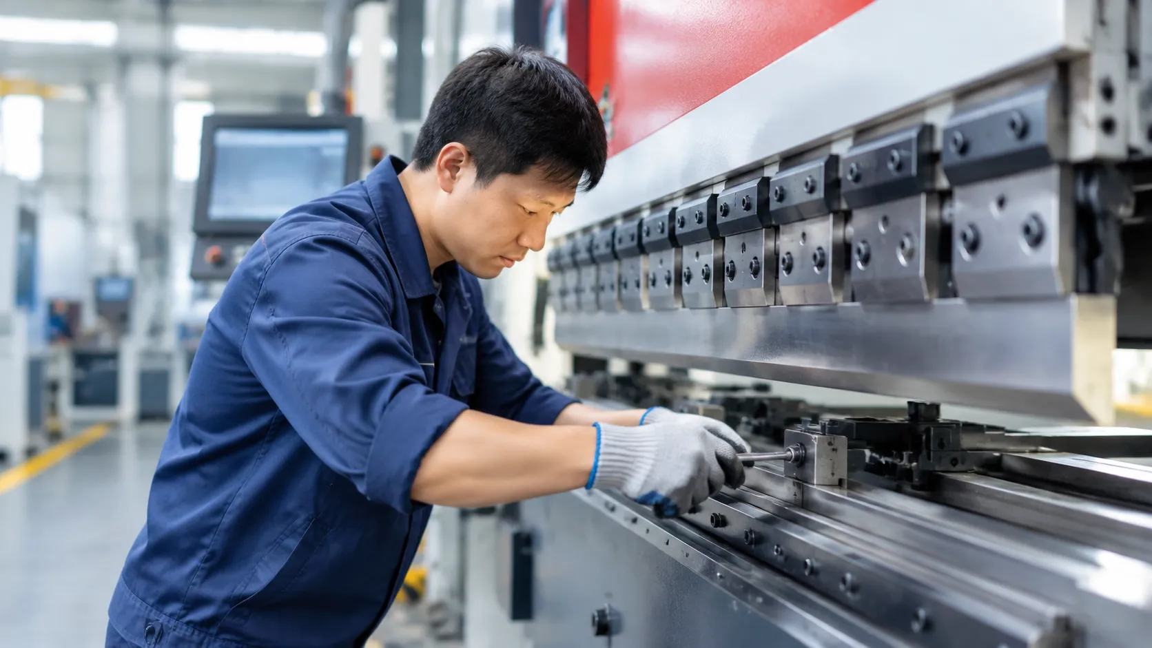
Hydraulic Oil Cleanliness and Servo Valve Filtration Standards
Proportional servo valves operate with micro-level spool clearances. Contaminated fluid is the fastest way to ruin them.
-
- Maintain strict oil cleanliness: We target an ISO 4406 cleanliness rating of 16/14/11 or better. Particulates cause valve sticking, erratic ram movement, and premature component failure.
- Filter replacement: Replace high-pressure servo line filter elements (typically rated at 3 to 5 microns) every 1,000 to 2,000 operating hours, or immediately if differential pressure indicators trigger.
- Monitor fluid condition: Sample and test the hydraulic oil every six months for viscosity loss, oxidation, and water contamination. Keep reservoir temperatures between 40°C and 55°C (104°F to 131°F) to preserve oil life and seal integrity.
Linear Scale Inspection, Cleaning, and Recalibration
Understanding what an electro hydraulic CNC press brake requires starts with its optical encoders. These linear scales track Y1 and Y2 cylinder positions down to microns, making them sensitive to workshop dust and oil mist.
-
- Regular scale wipe-downs: Inspect the protective covers and rubber lip seals monthly. Clean glass scales using non-abrasive optical cleaning wipes and pure isopropyl alcohol—never use harsh shop solvents.
- Reader head alignment: Verify that reader heads maintain proper air gaps and alignment along the scale track. Vibration from heavy plate forming can loosen mounting brackets over time.
- Reference recalibration: Run reference-point checks on the CNC controller periodically to catch positional drift before it produces angular errors across your bends.
Lubrication Routines for Backgauge Ballscrews and Guide Rails
The CNC backgauge delivers critical flange accuracy, so keeping the mechanical drive axes smooth prevents positioning errors.
-
- Clean and grease guide rails: Wipe down linear guide rails weekly to remove abrasive metal dust. Apply lithium-based EP2 grease or manufacturer-specified lubricant to all grease nipples on the carriage blocks.
- Service ball screws: Inspect the X-axis and R-axis ball screws for dryness or debris buildup. Re-lubricate ball nuts every 200 operating hours to minimize backlash and prevent binding.
- Wiper seals and hardware: Check the condition of end wipers on both screws and rails. Replace worn seals immediately to keep metal chips out of the bearing races.
Whether managing a compact shop setup or running high-capacity equipment like our 400 ton press brake for heavy duty metal forming, adhering to these routine checks preserves stroke repeatability, avoids costly valve replacements, and guarantees consistent bend angles across every shift.
Frequently Asked Questions
What does Y1 and Y2 mean on an electro-hydraulic press brake?
On an electro-hydraulic CNC press brake, Y1 and Y2 represent the fully independent vertical axes controlling the left and right hydraulic cylinders.
Unlike traditional machines that tie both cylinders together with a mechanical torsion bar, a closed-loop system monitors and drives each cylinder separately.
-
- Y1 Axis: Controls and monitors the left-hand cylinder position.
- Y2 Axis: Controls and monitors the right-hand cylinder position.
- Why it matters: Dedicated linear scales track both sides down to the micron. If one side encounters stiffer material or higher resistance, the CNC instantly adjusts fluid delivery to keep the ram completely parallel—or intentionally tilts it for tapered parts.
Can an electro-hydraulic press brake handle off-center bending safely?
Yes, off-center bending is one of the biggest operational advantages of an electro-hydraulic synchronization system.
When you bend heavy plate away from the machine centerline on an older mechanical torsion brake, the off-center load twists the torque tube, damages seals, and produces irregular angles.
On an electro-hydraulic machine, the proportional servo valves continuously throttle oil pressure between the two cylinders. If you run a high-tonnage job on the far left side of the bed, the Y1 cylinder increases force while Y2 throttles back, keeping the ram level without inducing mechanical strain or machine damage. This makes multi-station step bending and segmented tooling setups simple and repeatable.
How does automatic crowning improve bend accuracy?
Under heavy tonnage, every press brake bed and ram naturally deflects slightly in the center, causing the dreaded "canoe effect"—where your part is on-angle at both ends but wide open in the middle.
An automatic crowning compensation system counteracts this machine flex in real time:
-
- CNC Calculation: The controller analyzes sheet thickness, material tensile strength, tooling V-opening, and bend length before the ram touches the metal.
- Dynamic Compensation: The CNC drives motor-driven mechanical wedges or hydraulic cylinders built into the lower beam to lift the center bed.
- Uniform Angle: The punch penetrates the sheet at identical depths across the entire working length, delivering consistent angles from edge to edge without manual shimming.
What is the difference between open-loop and closed-loop hydraulic bending?
The core distinction comes down to real-time feedback and ram position control.
| Feature | Open-Loop Systems (Conventional) | Closed-Loop Systems (Electro-Hydraulic) |
|---|---|---|
| Position Feedback | None; oil simply pumps until a mechanical dead stop is hit | High-resolution optical scales constantly read actual ram position |
| Fluid Regulation | Directional spool valves open or close fully | Proportional servo valves modulate oil flow in microsecond intervals |
| Accuracy & Repeatability | Typically ±0.1 mm to ±0.5 mm | Typically ±0.01 mm (0.0004") |
| Load Adaptation | Cannot self-correct for off-center loads or oil temperature shifts | Instantly compensates for oil viscosity shifts and side loading |
| Energy Efficiency | Constant pump bypass generates excess heat and noise | Paired seamlessly with smart valving and hybrid press brakes to draw power only on demand |
In short, open-loop bending runs on blind pressure estimates, while closed-loop electro-hydraulic systems continuously verify and correct ram position throughout the stroke.