
Sheet Metal Fabrication Resources & Technical Library
Practical technical guides, machine selection resources, fabrication references, and troubleshooting insights for sheet metal engineers, production teams, and equipment buyers.
Explore knowledge covering laser cutting, bending, leveling, V grooving, plate rolling, shearing, and automated sheet metal production.
Explore Our Resource Library
Popular Equipment Topics
Core Engineering & Sheet Metal Machinery Knowledge Pillars
Haden bridges high-precision CNC machine tools with practical shop-floor fabrication through a structured technical documentation system. Navigate our dedicated portals for equipment sizing, operational formulas, manufacturing research, and commercial support.
Sheet Metal Buying Guides
Comprehensive equipment selection frameworks covering press brake tonnage sizing, high-performance sheet metal laser cutting machines , automation integration levels, and capital investment payback models.
- Tonnage & Bed Length Sizing
- Laser Power vs. Thickness Limits
- Automation Tiers & ROI Audits
Metal Processing Technical Guides
Field-tested operational manuals detailing precision bend deduction charts, gas parameters for advanced tube laser cutting machines , plate rolling pass formulas, and V-grooving depths.
- Bend Deduction & K-Factor Charts
- Assist Gas Dynamics & Kerf Offset
- Plate Rolling Pass Calculations
Industry Insights & Trends
Analysis covering automated bending cells, high-power laser cutting, fabrication technology developments, and energy-efficiency considerations across modern sheet metal production systems.
- Smart Factory Automation Trends
- Servo-Electric Energy Efficiency
- Fabrication Technology Insights
Fabrication & Machinery FAQs
Direct answers to common equipment and application questions covering CNC controls, machine configuration, maintenance, tooling, software integration, and after-sales support.
- Machine Configuration & Support
- Optics, Tooling & Maintenance
- CAD/CAM & Production Integration
Sheet Metal Machinery Selection & Capacity Evaluation Matrix
Selecting the correct sheet metal fabrication machinery requires balancing metallurgical limits, production volume, dynamic part geometry, and total capital expenditure. Haden provides an empirical sizing framework to configure industrial laser cutting machines, CNC press brakes, automated panel benders, and heavy-duty plate rolling lines with mathematical precision.
Fiber Laser Power vs. Material Thickness Selection
Proper sizing for dedicated sheet metal laser cutting machines matches continuous optical output power to plate thickness, thermal conductivity, and edge quality standards. Increasing power from 6kW to 12kW or 30kW shifts process limits from basic thermal separation to high-speed nitrogen vaporization, yielding dross-free edge finishes on mild steel, austenitic stainless steel, and structural aluminum alloys.
Bed configuration is equally critical: high-mix job shops require dual pallet shuttle tables for concurrent sheet loading, whereas high-volume rectangular component manufacturing benefits significantly from continuous coil-fed laser cutting machines and blanking lines.
Ideal for thick carbon steel (12mm–50mm). Low gas cost, controlled feed rates, oxidized edge requires post-treatment for paint adhesion.
Essential for stainless steel and aluminum. Prevents oxide discoloration and delivers weld-ready, clean micro-edges.
Optimized for 1mm–6mm carbon and galvanized sheet. Delivers cutting speeds comparable to N2 at up to 70% lower operating cost.
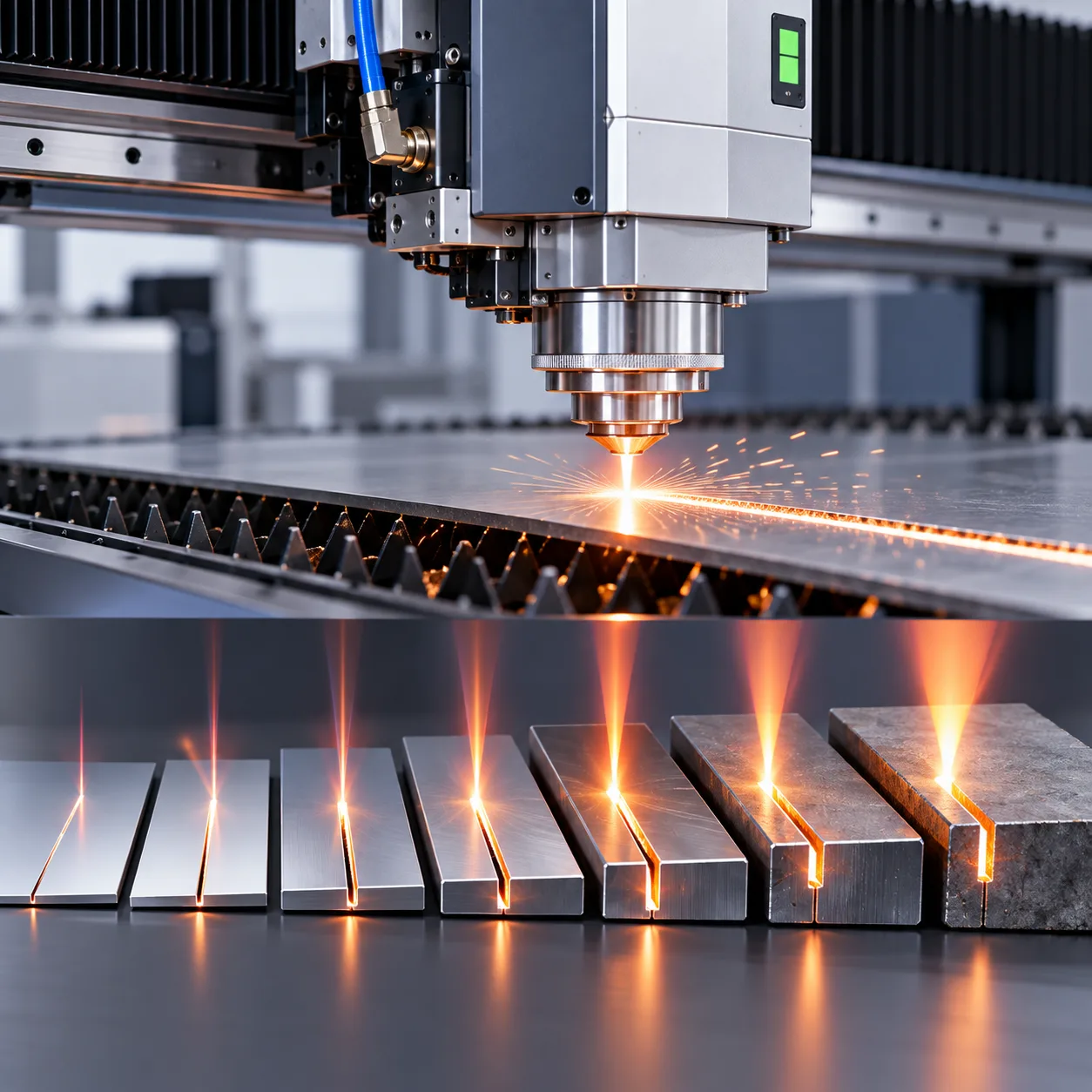
Haden Engineering Tip
Operating a 12kW laser at 70% duty cycle on 6mm carbon steel yields lower cost-per-part and extended optical protective window life compared to pushing a 6kW system at maximum continuous load.
| Laser Power | Carbon Steel (Max Clean) | Stainless Steel (N2 Cut) | Aluminum Alloy (N2 Cut) | Primary Assist Gas | Recommended Bed Architecture |
|---|---|---|---|---|---|
| 3 kW – 4 kW | 16 mm (O2) / 6 mm (Air) | 6 mm | 6 mm | O2 / High-Pressure N2 | Single / Dual Shuttle Table (3015) |
| 6 kW – 8 kW | 25 mm (O2) / 12 mm (Air) | 14 mm | 12 mm | N2 / Compressed Air / O2 | Dual Pallet Shuttle (3015 / 4020) |
| 12 kW – 15 kW | 40 mm (O2) / 20 mm (Air) | 30 mm | 25 mm | High-Pressure N2 / Dry Air | Automated Pallet Exchange & Tower |
| 20 kW – 30 kW+ | 50 mm+ (O2/N2) | 50 mm | 45 mm | Ultra-High-Pressure N2 / O2 | Heavy-Duty Gantry or Coil Blanking Line |
Require a Custom Machine Sizing & Tonnage Simulation?
Submit your DXF/STEP CAD part files to the Haden engineering team. We deliver complete machine capacity configuration reports, stroke profiles, bending collision checks, and cycle time calculations within 24 hours.
Sheet Metal Engineering Standards and Shop Floor Calculation Reference
Comprehensive calculation formulas, unfolding parameters, laser cutting tolerance charts, and metal forming standards verified for structural design engineers, CNC programmers, and workshop technicians.
Sheet Metal Unfold Calculations
Precise K-factor, bend allowance (BA), and bend deduction (BD) baseline values for soft aluminum, cold-rolled steel, galvanized sheet, and austenitic stainless steels (304/316).
- • Material-specific K-factor baseline tables
- • Empirical bend allowance formulas & charts
- • Accurate sheet metal bend deduction tables
Laser Cutting Tolerances
DIN EN ISO 9013 precision classifications, dynamic beam kerf width compensation values, and heat accumulation mitigation protocols for dense hole nesting on industrial laser cutting machines.
- • DIN EN ISO 9013 tolerance grade ranges
- • Beam kerf width compensation adjustments
- • Corner burn and thermal distortion controls
Precision V-Grooving & Shearing
Optimized residual thickness ratios (0.3S to 0.5S) for tight inside bend radii on decorative panels, plus hydraulic shearing and leveling metal forming standards.
- • V-groove residual thickness ratios (0.3S–0.5S)
- • Sharp bend radius criteria for architectural panels
- • Guillotine blade clearance percentage settings
K-Factor and Bend Allowance Reference
| Material Type | Thickness Range (mm) | K-Factor Range | Recommended Use |
|---|---|---|---|
| Soft Aluminum (1100-H14, 3003-H14) | 0.8–3.0 | 0.33–0.35 | Architectural facades, decorative covers, non-structural enclosures |
| Cold-Rolled Steel (SPCC, DC01) | 0.5–4.0 | 0.32–0.36 | Standard electrical cabinets, machine chassis, structural brackets |
| Galvanized Sheet (SGCC, DX51D) | 0.8–3.2 | 0.34–0.37 | HVAC ducting, outdoor enclosures, automotive inner panels |
| Austenitic Stainless Steel (SUS304, 1.4301) | 1.0–6.0 | 0.38–0.42 | Food processing equipment, medical housings, cleanroom furniture |
| Austenitic Stainless Steel (SUS316L, 1.4404) | 1.0–6.0 | 0.40–0.44 | Marine hardware, chemical process vessels, pharmaceutical cabinets |
Engineering Note: K-factor shifts according to die opening ratio (V-width), punch tip radius, and material tensile strength. Haden CNC machine controllers feature embedded, factory-validated material compensation databases and dynamic adaptive algorithms that automatically calibrate bend deductions.
DIN EN ISO 9013 Laser Cutting Tolerance Classifications
| Tolerance Grade | Positional Tolerance (mm) | Surface Roughness (Ra) | Typical Applications |
|---|---|---|---|
| Grade 1 (Ultra-Precision) | ±0.05 to ±0.10 | 1.6 µm (Rz5 ≤ 10 µm) | Precision electrical contacts, optical instrument housings, aerospace shims |
| Grade 2 (High Precision) | ±0.10 to ±0.20 | 3.2 µm (Rz5 ≤ 20 µm) | Medical chassis, automotive sensor brackets, server rack sub-assemblies |
| Grade 3 (Industrial Standard) | ±0.20 to ±0.35 | 6.3 µm (Rz5 ≤ 40 µm) | General industrial enclosures, control cabinets, machinery protective guards |
| Grade 4 (Heavy Structural) | ±0.35 to ±0.60 | 12.5 µm (Rz5 ≤ 80 µm) | Heavy equipment baseplates, construction brackets, thick gusset plates |
Kerf Compensation Guidance: Fiber laser kerf widths typically measure 0.12–0.28 mm depending on nozzle diameter, laser power, and assist gas pressure. Apply precise CNC lead-in offsets on high-performance sheet metal laser cutting machines to preserve ISO 9013 Class 1 and Class 2 dimensional integrity.
Precision V-Grooving Parameters for Tight Bend Radii
| Sheet Thickness (S, mm) | Residual Thickness Range | Minimum Bend Radius (R) | Strength Reduction (%) |
|---|---|---|---|
| 0.8 | 0.24–0.32 mm (0.30S–0.40S) | R < 0.25 mm | 15–20% (Aesthetic cladding, light trims) |
| 1.0 | 0.30–0.45 mm (0.30S–0.45S) | R < 0.30 mm | 18–24% (Elevator cabins, architectural door frames) |
| 1.5 | 0.45–0.68 mm (0.30S–0.45S) | R < 0.40 mm | 20–28% (Display consoles, high-end appliance exteriors) |
| 2.0 | 0.60–0.90 mm (0.30S–0.45S) | R < 0.50 mm | 22–30% (High-precision architectural metalwork) |
| 3.0 | 0.90–1.35 mm (0.30S–0.45S) | R < 0.70 mm | 25–35% (Heavy decorative profiles, curtain wall panels) |
Design Guidance: Residual thickness below 0.30S risks fracture along bend lines in cold-worked alloys. For structural components carrying dynamic mechanical loads, limit grooving depths to maintain strength retention above 80% or specify internal stiffener ribs.
Shearing and Coil Leveling Specifications
| Parameter | Material Type | Recommended Setting | Impact / Notes |
|---|---|---|---|
| Guillotine Blade Clearance | Cold-Rolled Carbon Steel (0.5–6.0 mm) | 5–8% of sheet thickness | Ensures clean shear fraction ratio (>60%) and prevents edge rollover |
| Guillotine Blade Clearance | Austenitic Stainless Steel (1.0–5.0 mm) | 8–12% of sheet thickness | Prevents rapid blade binding and micro-chipping caused by work-hardening |
| Leveling Roll Penetration (Entry / Exit) | Carbon Steel Sheet & Plate (1.5–10.0 mm) | 80–120% yield plastic strain | Neutralizes internal stress memory, eliminating edge waves and center buckles |
| Leveling Roll Penetration (Entry / Exit) | Stainless & High-Yield Alloys (0.8–6.0 mm) | 60–90% controlled strain profile | Eliminates sheet cross-bow and longitudinal curl without degrading surface finish |
Quality Note: Precision multi-roll leveling ensures laser-flat blanks with minimal residual stress, eliminating cutting head collision risks on automated systems and inline coil-fed laser cutting machines.
Sheet Metal Process Comparison and Technology Trade-Off Analysis
Selecting the optimal manufacturing route requires balancing capital equipment expenditure, batch volume flexibility, geometric constraints, edge tolerance standards, and shop-floor labor overhead. Modern high-mix fabrication operations rarely rely on a single equipment class; instead, manufacturing engineers evaluate technical trade-offs across bending kinematic systems, press drive architectures, and thermal blanking platforms to achieve peak unit profitability.
This engineering comparison breaks down critical sheet metal processing trade-offs: flexible panel benders versus multi-axis CNC press brakes, servo electric versus hydraulic bending systems, and high-power fiber laser cutting versus plasma and mechanical CNC punching. Use these empirical engineering metrics to evaluate cycle times, eliminate production bottlenecks, and maximize part accuracy across thin gauge and heavy plate fabrications.
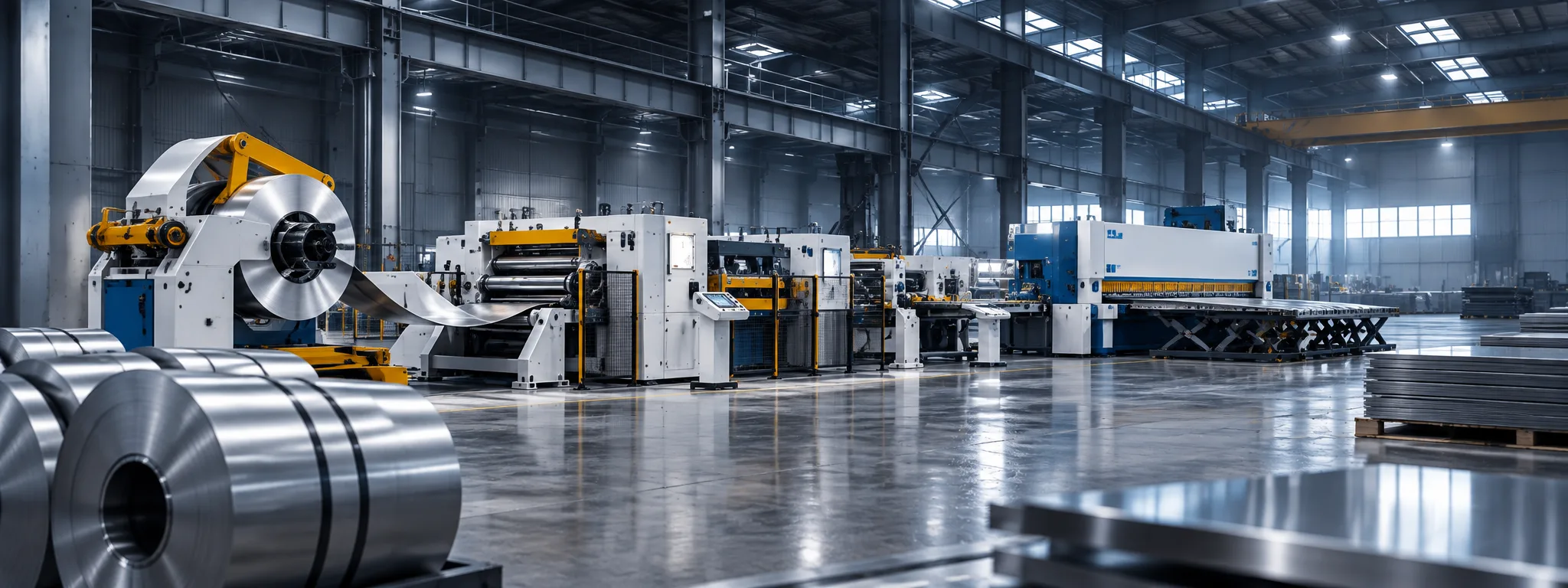
Data-driven evaluation of cycle times, setup parameters, thermal repeatability, and energy efficiency across industrial sheet metal forming systems.
Panel Bender vs. Press Brake: Kinematics and Volume Flexibility
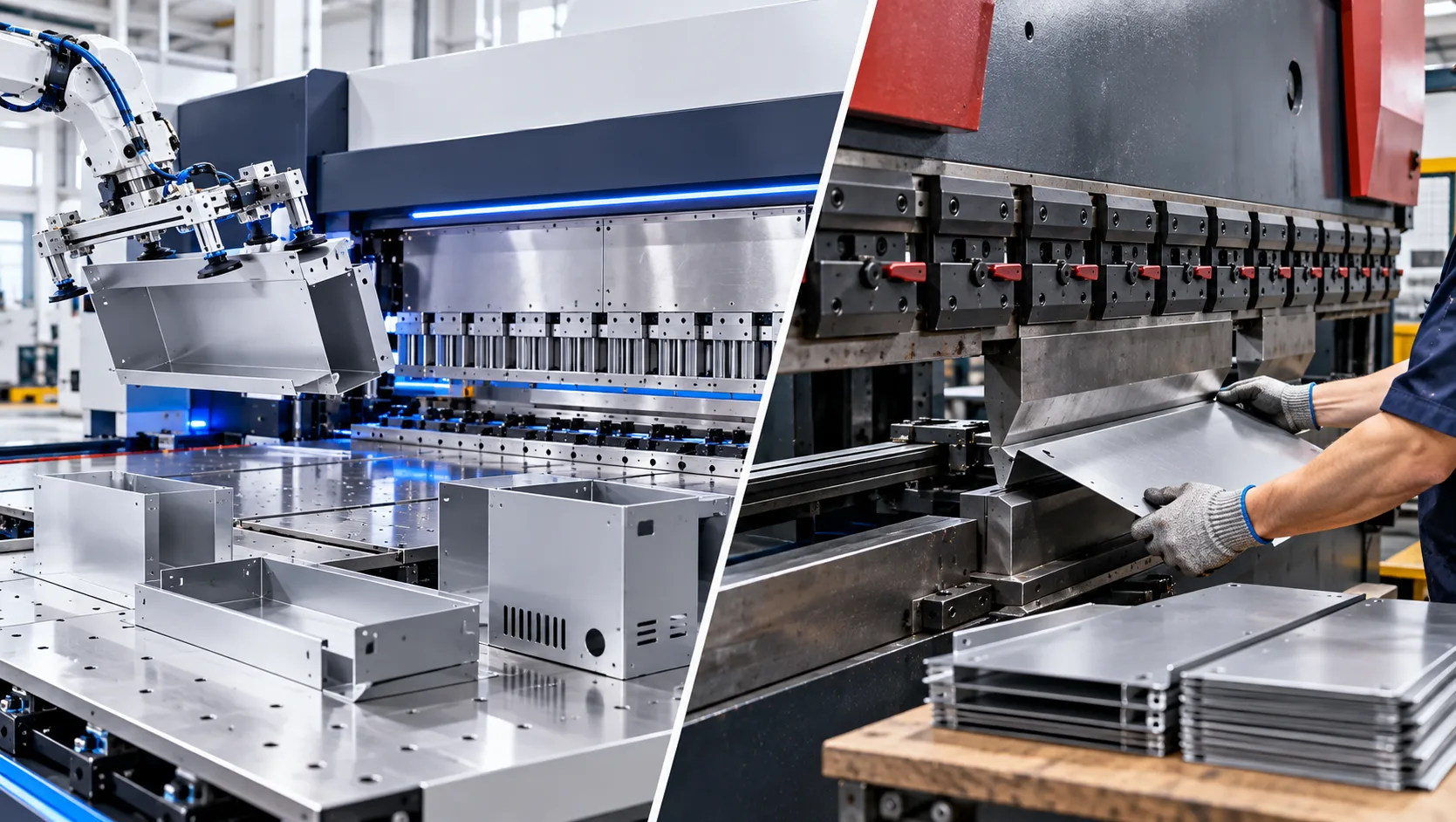
Evaluating a panel bender vs press brake depends on workpiece geometry, sheet thickness, batch variation, and part handling ergonomics. While automated panel benders provide rapid multi-edge folding on thin sheets with universal tooling, multi-axis CNC press brakes deliver high forming tonnage, large open daylight heights, and versatile tooling setups required for complex brackets, heavy enclosures, and thick plate profiles.
Flexible Panel Benders
High-Speed Thin SheetOperates with synchronized upper and lower bending blades that interpolate around sheet edges. The raw sheet is clamped horizontally by a servo manipulator, allowing the bending blades to form positive and negative bends automatically without manual part flipping.
- Forming Speed: Sub-second individual bends (0.2 to 0.4 seconds per stroke); completes a full 4-sided boxed panel in under 25 seconds.
- Tooling Changeover: Universal bending blades adapt automatically via software control, eliminating manual punch and die setups.
- Operator Ergonomics: Single-point sheet loading; motorized manipulators manage all rotational positioning, reducing operator fatigue.
- Dimensional Limits: Maximum material gauge restricted to 3.2 mm carbon steel (2.2 mm stainless); internal return flange depths are strictly limited.
Electrical enclosures, architectural facade cassettes, HVAC duct panels, lighting fixtures, and commercial refrigeration housings.
CNC Press Brakes
Heavy-Duty VersatilityUtilizes matching top punch and bottom V-die tooling driven by a synchronized vertical ram. Configurable in servo electric, electro-hydraulic hybrid, or synchronous hydraulic architectures with customizable throat depths.
- Material Flexibility: Processes sheet metals from 0.5 mm up to 32 mm+ heavy plate, with machine capacities ranging from 40 tons to over 2,000 tons.
- Geometric Capability: Accommodates deep box profiles, acute channels, heavy hemming, gooseneck tool clearances, and step bending.
- Setup Time: Requires mechanical punch and die changes, segmented tool staging, and backgauge adjustments between batch runs.
- Labor Dependency: Large, unwieldy panels require multiple operators or synchronized sheet-following supports to avoid back-bend deformities.
Heavy equipment chassis, structural brackets, agricultural machinery, custom job-shop fabrications, and thick-plate profiles.
Panel Bender vs. CNC Press Brake
Reference values for preliminary equipment selection
| Technical Parameter | Flexible Panel Bender | CNC Press Brake | Engineering Recommendation |
|---|---|---|---|
| Material Thickness Range | 0.4 mm to 3.2 mm (Mild Steel) | 0.5 mm to 32.0 mm+ | Select panel benders for ≤ 2.5 mm; utilize press brakes for heavy plate > 3.0 mm |
| 4-Bend Box Cycle Time | 18 to 28 seconds Total handling + bending | 65 to 110 seconds Manual rotation & positioning | Panel benders can significantly reduce handling time on repetitive rectangular box assemblies. |
| Tooling Requirements | Universal segmented bending blades with CNC-controlled setup | Application-specific punches, dies and segmented tooling | Press brake tooling requirements vary with bend radius, material thickness and part geometry. |
| Batch Flexibility | CNC program-based changeover | Tooling and backgauge setup may be required between jobs | Panel benders are well suited to high-mix automated panel production. |
| Geometric Freedom | Optimized for panels, shallow boxes, hems and offset folds | Broad forming flexibility for channels, brackets and structural components | CNC press brakes remain suitable where deeper profiles, heavier materials or specialized tooling are required. |
Selection Note: Final machine configuration should be based on actual material, thickness, bend geometry, flange dimensions and production requirements.
| Technical Parameter | Flexible Panel Bender | CNC Press Brake (Hydraulic/Electric) | Engineering Recommendation |
|---|---|---|---|
| Material Thickness Range | 0.4 mm to 3.2 mm (Mild Steel) | 0.5 mm to 32.0 mm+ | Select panel benders for ≤ 2.5 mm; utilize press brakes for heavy plate > 3.0 mm |
| 4-Bend Box Cycle Time | 18 to 28 seconds (Total handling + bending) | 65 to 110 seconds (Manual rotation & positioning) | Panel benders achieve 3x to 4x throughput on rectangular box assemblies |
| Tooling Capital Expense | Universal segmented blades included; near-zero tooling wear | Specialized punches, dies, and multi-V blocks ($5,000 to $40,000/yr) | Press brake tooling costs scale directly with part radii and geometry complexity |
| Batch Flexibility (Lot Size 1) | Instant program changeover via CNC software parametric models | Requires mechanical tool realignment and backgauge zeroing | Panel benders excel in high-mix automated kit production environments |
| Geometric Freedom | Optimized for panels, shallow boxes, hems, and offset folds | Broad geometric freedom (Deep channels, cones, heavy structural sections) | CNC press brakes remain essential for heavy multi-flange structural components |
Servo Electric vs. Hydraulic Bending and Electro-Hydraulic Hybrid Drives
The drive architecture of a press brake directly governs power consumption, thermal stability across multi-shift production, operational noise levels, and maintenance downtime. Comparing servo electric vs hydraulic bending architectures reveals that direct-drive servo and electro-hydraulic hybrid systems eliminate hydraulic thermal drift, provide sub-micron ram positioning, and reduce electrical utility consumption by 30% to 60%.
All-Electric Servo Drive
Max Energy EfficiencyDirect dual-servo motors driving high-precision planetary roller screws or dual-pulley synchronous belt systems. Completely 100% oil-free operation.
- Energy Savings: 50% to 65%
- Ram Repeatability: ± 0.001 mm
- Acoustic Level: < 60 dB (Ultra-quiet)
- Standard Tonnage Range: 35T to 150T
- Hydraulic Thermal Drift: Zero (No Fluid)
Best for: Cleanroom environments, medical equipment, electronics, and rapid thin-gauge precision bending.
Electro-Hydraulic Hybrid
Optimal Power & SpeedBi-directional AC servo motors power localized closed-loop hydraulic pumps mounted directly on each cylinder, utilizing under 20% of standard fluid volume.
- Energy Savings: 35% to 50%
- Ram Repeatability: ± 0.003 mm
- Acoustic Level: < 66 dB
- Standard Tonnage Range: 100T to 600T
- Hydraulic Thermal Drift: Negligible
Best for: High-capacity multi-shift manufacturing requiring both high tonnage and continuous positional precision.
Conventional Proportional Hydraulic
Heavy StructuralCentral AC induction motor continuously drives a large hydraulic reservoir through high-speed proportional valves and complex manifold blocks.
- Energy Savings: Baseline Standard (0%)
- Ram Repeatability: ± 0.010 mm
- Acoustic Level: 75 to 84 dB
- Standard Tonnage Range: Up to 3,000T+ (Tandem)
- Hydraulic Thermal Drift: Moderate to High
Best for: Heavy infrastructure plate bending, shipbuilding frames, structural steel, and cost-sensitive initial installations.
Thermal Stability & Operating Cost Considerations
Thermodynamic Stability & First-Part Accuracy
In conventional hydraulic systems, continuous fluid recirculation increases oil temperatures from 20°C during morning startup to over 55°C after hours of operation. This fluid viscosity change causes proportional valve response lag, requiring press brake operators to manually adjust bend angles by 0.5° to 1.5° across a working shift.
By contrast, Servo Electric and Electro-Hydraulic Hybrid architectures operate motors strictly on-demand during active ram movement. Fluid and drive temperatures remain stabilized near ambient levels, guaranteeing that the first formed part matches the 500th part within ±0.2° angular tolerance without manual operator recalibration.
5-Year Energy Consumption & Fluid Maintenance TCO
On an industrial two-shift schedule (4,000 operational hours per year), a conventional 175-ton hydraulic press brake consumes roughly 34,000 kWh annually while requiring 350 liters of oil replacement, seal replacements, and filter maintenance every 2,500 hours.
A comparable Servo-Electric or Hybrid system slashes energy draw to under 14,500 kWh annually and uses sealed or oil-free drives, generating over $18,000 in direct utility savings and eliminating hazardous hydraulic fluid disposal expenses over a 5-year production cycle.
Engineering Note: Actual energy consumption, thermal behavior and operating cost vary with machine tonnage, drive configuration, duty cycle, material, electricity rates and production schedule.
Thermodynamic Stability & First-Part Accuracy
In conventional hydraulic systems, continuous fluid recirculation increases oil temperatures from 20°C during morning startup to over 55°C after hours of operation. This fluid viscosity change causes proportional valve response lag, requiring press brake operators to manually adjust bend angles by 0.5° to 1.5° across a working shift.
By contrast, Servo Electric and Electro-Hydraulic Hybrid architectures operate motors strictly on-demand during active ram movement. Fluid and drive temperatures remain stabilized near ambient levels, guaranteeing that the first formed part matches the 500th part within ±0.2° angular tolerance without manual operator recalibration.
5-Year Energy Consumption & Fluid Maintenance TCO
On an industrial two-shift schedule (4,000 operational hours per year), a conventional 175-ton hydraulic press brake consumes roughly 34,000 kWh annually while requiring 350 liters of oil replacement, seal replacements, and filter maintenance every 2,500 hours.
A comparable Servo-Electric or Hybrid system slashes energy draw to under 14,500 kWh annually and uses sealed or oil-free drives, generating over $18,000 in direct utility savings and eliminating hazardous hydraulic fluid disposal expenses over a 5-year production cycle.
Fiber Laser Cutting vs. High-Definition Plasma vs. CNC Turret Punching
The blanking and sheet profiling stage establishes the precision and throughput of downstream bending and welding operations. While modern sheet metal laser cutting machines utilizing high-power fiber lasers have become the benchmark for high-mix contour cutting, applications requiring localized three-dimensional forming (such as louvers, countersinks, and extrusions) or thick structural steel plate present clear process trade-offs.
| Process Metric | High-Power Fiber Laser (6kW to 30kW) | High-Definition Plasma | CNC Turret Punching |
|---|---|---|---|
| Optimal Thickness Range | 0.5 mm to 40.0 mm (Comprehensive range) | 8.0 mm to 80.0 mm+ (Heavy structural plate) | 0.5 mm to 4.5 mm (Thin gauge only) |
| Cut Edge Quality (ISO 9013 Ra) | Ra 3.2 to 12.5 µm (Dross-free finish) | Ra 25.0 to 50.0 µm (Bevel edge risk) | Sheared edge with characteristic rollover & burr |
| Geometric Freedom & Kerf Width | Unrestricted; narrow kerf width (~0.12 to 0.20 mm) | Moderate; kerf width 1.5 mm to 3.8 mm | Limited by physical tool station geometry |
| In-Line Forming Capability | Cutting only (No 3D mechanical deformation) | Thermal cutting and heavy beveling only | Forms louvers, countersinks, ribs, and tapped holes |
| Nesting Material Utilization | 88% to 95% (Common-line cutting & micro-joints) | 76% to 84% (Requires larger skeleton borders) | 72% to 83% (Constrained by sheet clamp dead-zones) |
| Tooling & Consumable Costs | Focus lenses, nozzles, and assist gases (N2, O2, Air) | Electrodes, swirl rings, nozzles (Frequent replacement) | Mechanical punch sharpening, station tooling sets |
Blanking Technology Selection Takeaway
High-power fiber laser cutting machines provide unmatched linear cutting speeds (exceeding 60 m/min in thin stainless steel) and eliminate physical tooling constraints, making it the primary choice for flexible contour profiling. However, for manufacturing environments running recurring chassis with heavy stamping, card guides, and formed louvers, integrating a dedicated CNC turret punch or a combination laser-punching cell minimizes secondary handling operations.
Optimizing Equipment Allocation Across Modern Sheet Metal Workcells
World-class fabrication facilities maximize return on capital by deploying an integrated machinery matrix: routing high-volume, thin-gauge panels to automated panel benders while reserving heavy-tonnage CNC press brakes for complex structural bend sequences.
Analyze 3D CAD step models to calculate return flange depths, box aspect ratios, and tool interference thresholds.
Separate high-runner thin-gauge panels from heavy structural weldments to optimize cell routing and eliminate setup bottlenecks.
Evaluate High-Pressure Nitrogen edge purity against Ultra-High-Pressure Compressed Air cutting to reduce operating gas costs by up to 70%.
Haden manufactures a comprehensive industrial machinery portfolio across versatile sheet and tube laser cutting machines, CNC press brakes, flexible panel benders, plate rolls, and V-groovers, delivering unbiased, engineering-backed machinery configurations tailored to your production drawings.
Sheet Metal Defect Diagnostics and Shop-Floor Optimization Guide
Production bottlenecks, unpredictable scrap rates, and out-of-tolerance workpieces typically originate from subtle mismatches between CNC machine parameters, tooling geometry, and raw material mechanical properties. This shop-floor diagnostic library provides manufacturing engineers, machine programmers, and setup technicians with systematic root-cause troubleshooting workflows to optimize industrial laser cutting machines, eliminate cutting burrs, manage bending springback, prevent plate rolling distortion, and neutralize residual leveling stress across industrial fabrication lines.
Fiber Laser Cutting Defect Diagnostics & Burr Elimination
Isolating melt dross, localized overburns, rough edge striations, and piercing instability on high-precision sheet metal laser cutting machines across mild steel, stainless steel, and aluminum alloys.
Bottom-Edge Melt Dross & Slag Accumulation
Molten metal fails to evacuate fully from the lower kerf boundary, leaving continuous, adherent dross burrs that require secondary manual deburring.
Primary Root Causes: Beam focal point positioned too high above the bottom sheet surface; assist gas pressure insufficient to clear melt pool viscosity; cutting travel speed exceeds optimal energy balance.
Corner Overburning & Thermal Gouging
Acute radii and sharp internal corners overheat during axis deceleration, triggering runaway exothermic oxidation, melted profiles, and loss of dimensional accuracy.
Primary Root Causes: Excessive continuous laser output during corner slowdown; excessive oxygen delivery pressure feeding uncontrolled exothermic combustion.
Severe Kerf Striation & Excessive Surface Roughness
Cut edges display deep horizontal drag lines, erratic vertical washboard waves, and high surface roughness values (exceeding ISO 9013 Range 2/3 limits).
Primary Root Causes: Nozzle mechanical runout or partial bore spatter occlusion; kinematic axis backlash; turbulent assist gas stream; improper focal waist position.
Piercing Blowout & Slag Eruption
Initial plate penetration detonates with heavy molten spatter, contaminating optical cover slides, ruining nozzle tips, and damaging starting cut geometries.
Primary Root Causes: Single-stage high-pressure blast piercing without controlled energy ramping; contaminated optical slide causing thermal focus drift; inadequate pierce dwell.
Shop-Floor Parameter Calibration Matrix
Quick-reference corrective thresholds for machine setup, CNC offset tuning, and regular preventive quality audits.
| Manufacturing Process | Defect Classification | Critical Machine Variable | Diagnostic Indicator | Corrective Action Window |
|---|---|---|---|---|
| Fiber Laser Cutting | Bottom Dross (Mild Steel) | Oxygen Purity & Pressure Balance | Purity < 99.5% / Pressure < 0.5 bar | Verify 99.95% Purity; set assist pressure to 0.6–0.9 bar |
| Fiber Laser Cutting | Striation Washout (Stainless) | Focal Position & Nozzle Centering | Beam Offset > ±0.20 mm | Adjust focus to -2.0 mm to -3.5 mm into sheet thickness |
| CNC Press Brake | Mid-Bed Angle Opening (Canoeing) | Mechanical Crowning Preload | Center-to-End Spread > 0.5° | Increase CNC motorized crowning compensation by +10% to +15% |
| CNC Press Brake | Shoulder Galling & Scratches | V-Die Shoulder Friction Coefficient | Direct Tool-to-Sheet Contact | Install polyurethane film or upgrade to Rolla-V tooling |
| Plate Rolling | Unbent Flat End Overrun | Bottom Roll Pinch Clamping Force | Flat Length > 2.0x Thickness | Pre-bend edge at 85%–95% rated hydraulic pinch pressure |
| Precision Leveling | Center Buckles (Oil Canning) | Back-Up Roll Radial Profile | Center Fibers Over-Stretched | Retract center back-ups; increase pressure on lateral rolls |
Need On-Site Defect Auditing & Custom Parameter Optimization?
Haden maintains a worldwide application engineering team delivering on-site factory process audits, dynamic laser interferometer tool calibrations, and master-level operator training programs to guarantee scrap reduction and extreme part repeatability.
Machinery Lifecycle Preventive Maintenance Protocols and Operational Procedures
Unplanned downtime when operating high-output sheet metal laser cutting machines erodes operating margins, disrupts delivery cycles, and degrades critical dimensional tolerances. Implementing a structured preventive maintenance schedule preserves positioning repeatability, mitigates unexpected thermal drift, and extends the operational lifespan of high-power laser cutting machines, proportional hydraulic manifolds, and linear motion drives. Haden fabrication machinery features engineered service access ports, integrated diagnostic monitoring subroutines, and heavy-duty mechanical assemblies designed to simplify shift-level inspections and ensure uncompromising multi-shift production stability.
Standardized Milestone Maintenance Schedule
Execute inspection routines systematically across shift handovers, operational runtime thresholds, and annual recalibration milestones.
Shift Handover & Daily Pre-Flight Inspection
Verify critical fluid levels, optical cleanliness, and machine reference datum points prior to starting production shifts.
- Verify fiber laser water chiller dual-circuit temperature differential (ambient vs. optical loop within ±0.5°C).
- Execute laser optics maintenance cover slide contamination check under clean white light inspection pen.
- Inspect CNC press brake hydraulic reservoir sight glass for correct oil level and verify zero seal leakage.
- Zero backgauge axes (X, R, Z1, Z2) and verify optical safety light curtain alignment before running workpieces.
Lubrication, Filtration & Mechanical Servicing
Replenish centralized lubricants, purge particulate contaminants, and clean critical motion components.
- Replenish automated CNC machine lubrication reservoirs with ISO VG 68 slide oil or NLGI 2 lithium grease.
- Wipe and degrease linear guideways, dual ball screws, and rack-and-pinion transmission tracks before re-greasing.
- Check hydraulic return line filter contamination indicator; replace 10-micron filter cartridge if differential pressure alarms trip.
- Purge assist gas high-pressure pneumatic particulate traps and drain condensed moisture from shop air lines.
Hydraulic Integrity & Electro-Mechanical Inspection
Conduct oil degradation testing, check valve manifold seatings, and inspect cable drag chains.
- Extract hydraulic fluid sample for NAS 1638 / ISO 4406 particulate cleanliness and kinematic viscosity testing.
- Inspect proportional directional valve solenoids, check valves, and cylinder seal ring wear on press brakes.
- Inspect high-flex servo motor feedback cables and fiber delivery conduits inside high-speed drag chains.
- Clean electrical cabinet heat exchangers and inspect cooling fan tachometer output for cooling capacity loss.
Geometric Recalibration & Dynamic Accuracy Verification
Verify multi-axis positioning accuracy with laser interferometry and recalibrate mechanical crowning compensation.
- Execute full-stroke laser interferometer positioning and repeatability measurement on X, Y, and Z axes.
- Recalibrate CNC dynamic hydraulic and mechanical crowning systems using precision dial test indicators.
- Perform ultrasonic cleaning and alignment of optical linear glass scales (Heidenhain / Givi Misure).
- Perform infrared thermographic scan of power distribution busbars, contactors, and servo drive power terminals.
Consumables Lifecycle Management Dashboard
Standard replacement intervals, wear symptoms, and operational risk mitigation guidelines.
| Component Category | Nominal Service Life | Observable Wear Indicator | Preventive Action Protocol | Operational Risk if Neglected |
|---|---|---|---|---|
| Fiber Laser Cutting Nozzle (Single/Double Chrome) | 80 - 150 Arc Hours | Orifice ovality distortion > 0.1 mm, internal spatter adhesion | Automated nozzle cleaning cycle; replace and center via capacitive sensor | Turbulent gas flow causing excessive bottom dross and edge roughness |
| Optical Focus Protective Cover Glass | 150 - 300 Arc Hours | Thermal focal shift, surface pitting under microscope inspection | Replace in cleanroom environment; never touch quartz substrate with bare hands | Catastrophic beam absorption, focusing lens explosion, optical head loss |
| Capacitive Sensor Ceramic Ring | 600 - 1,000 Hours | Hairline ceramic cracking, RF signal drift, loose nozzle thread | Inspect ceramic body integrity; torque to 1.5 Nm using insulated tools | Height tracking failure resulting in rapid laser cutting head collision |
| CNC Press Brake Hardened Punch & Die Tooling | 2,000 - 4,000 Bends/Mtr | Tip radius deformation > 0.05 mm, flaking on 42CrMo surface hardening | Check tip alignment with optical comparator; regrind or swap segment tooling | Flange angle inconsistency across bed, visible workpiece scoring marks |
| Hydraulic Proportional Return Oil Filter | 1,500 - 2,000 Hours | Differential pressure gauge redline indicator, oil bubbling | Replace micro-glass fiber element; inspect magnetic trap for steel shavings | Spool valve jamming, cylinder synchronization loss, pump cavitation |
| Hydraulic Guillotine Shear High-Carbon Blades | 100,000 - 200,000 Cuts | Cutting edge micro-chipping > 0.2 mm, excessive material burr height | Rotate blade to unused cutting edge (4-edge design) or precision surface grind | Edge tear-out, sheet twisting, overload tripping on hydraulic pump |
Fluid and Lubrication Standards
Contaminated lubricant accounts for over 70% of premature ball screw and hydraulic pump failures. Maintain strict fluid cleanliness standards:
- Hydraulic Systems: Use anti-wear mineral oils (ISO VG 46 or 68) with zinc-free additives to protect proportional servo valves.
- Linear Drives: Centralized automatic pump systems require synthetic grease (NLGI grade 00 or 0) for consistent distribution across multi-meter gantries.
Cleanroom Optical Handling
Protecting high-power optical heads on flatbed and specialized tube laser cutting machines requires absolute cleanroom protocols during maintenance intervals:
- Environmental Isolation: Always perform protective window replacement inside a dust-free enclosure or laminar flow bench.
- Cleaning Solvents: Apply only high-purity spectroscopic grade isopropyl alcohol (IPA > 99.9%) using lint-free optical lens tissue swabs.
Haden Engineered Maintenance Ports
Haden machinery designs incorporate dedicated quick-access panels and integrated diagnostic sensors to cut maintenance hours:
- Centralized Grease Manifolds: Single-point external greasing blocks eliminate the need to crawl inside machine chassis.
- Digital Pressure Transducers: Real-time hydraulic pressure and filter backpressure feedback visible directly on the CNC HMI.
Sheet Metal Machinery FAQs: Technical & Procurement Solutions
Authoritative engineering answers covering machine tonnage sizing, fiber laser assist gas dynamics, open CNC Industry 4.0 integration, custom machine tool fabrication, and international service standards. Explore practical resolutions curated by the Haden technical team to guide procurement decisions and optimize shop-floor fabrication efficiency.
Have a Specific Part Drawing or Non-Standard Specification?
Haden senior application engineers provide complimentary CAD/CAM part assessments, bending tonnage calculations, and cycle time simulations within 24 hours.
Build the Right Machine
Around Your Production.
Share your part drawings, material specifications, thickness range, production volume, and process requirements. Haden application engineers can evaluate the application and develop a machine configuration around your actual production needs.
From standalone equipment to integrated sheet metal production systems, the evaluation can cover machine capacity, tooling, automation, process layout, and production considerations.
What to Send Our Engineering Team
A few basic production details allow our team to evaluate the application more efficiently.