The Core Mechanical Principle: Three-Point Continuous Bending
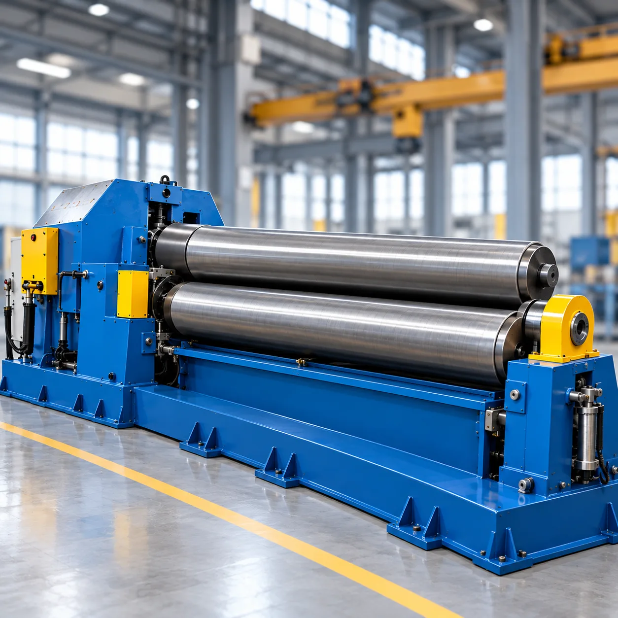
At its engineering core, the plate rolling machine working principle relies on continuous, multi-point plastic deformation. When we feed a flat metal sheet between the work rolls, the machine creates a three-point bending system that subjects the plate to targeted bending moments, transforming flat stock into precise cylindrical, conical, or arc segments.
Stress-Strain Distribution Across the Neutral Axis
During the continuous bending cycle, internal stress shifts across the plate thickness:
-
- Outer Surface (Tensile Zone): Stretches under extreme tension, expanding beyond the elastic limit into plastic yield.
- Neutral Axis: Retains its original length with zero normal strain, serving as the geometric boundary between opposing forces.
- Inner Surface (Compression Zone): Undergoes heavy compressive stress, resulting in structural material shortening and thickening.
Plate Rolling Force & Material Deformation
[ Upper Roll Force: Downward Load ] ↓
=================== Plate ===================
[+] Tension (Outer Surface Yield)
--- Neutral Axis (Zero Strain)
[-] Compression (Inner Surface Yield)
=============================================
↑ ↑
[ Lower Roll 1 ] [ Lower Roll 2 ]
Achieving Permanent Plastic Deformation and Managing Springback
To achieve a permanent radius, the applied mechanical or hydraulic force must exceed the material's yield strength. Once the outer and inner fibers exceed this threshold, the metal takes a permanent set.
Because every metal retains an elastic zone near the neutral axis, elastic recovery (springback) occurs immediately after the sheet exits the roll contact zone. We compensate for this springback by dynamically adjusting roll penetration, deliberately over-bending the plate to a tighter initial radius so it settles at the exact target diameter upon release.
Normal Force Transmission and Roll Friction Torque
Continuous plate advancement depends on two interacting mechanical forces:
-
- Normal Clamping Force: Hydraulic cylinders or mechanical drive screws apply high vertical clamping force, locking the plate firmly between the rolls.
- Friction Torque Transfer: Motorized drive rolls transfer rotary torque through surface friction. This continuous traction draws the plate smoothly through the bend zone without surface scuffing or slippage.
Mathematical Determination of Curvature Radius
The resulting curvature radius is governed by the spatial geometry of the roll contact points:
-
Roll Center Distance (a): The fixed or adjustable horizontal span between the bottom support rolls.
-
Roll Vertical Offset (y): The stroke depth or vertical penetration of the pressing roll.
-
Material Properties: The specific yield point, sheet thickness, and elastic modulus of the workpiece.
By controlling the vertical stroke and side roll positioning with micron-level precision, we precisely regulate the bending moment arm to produce uniform, tight-tolerance cylindrical shells.
Working Principles by Machine Kinematic Configuration
Understanding the plate rolling machine working principle requires looking at how different roll configurations apply mechanical forces. The way rolls move, clamp, and deliver torque determines both forming accuracy and edge pre-bending efficiency across different plate thicknesses.
Three-Roll Symmetrical Pyramid Machines and Unbent Flat Ends
In a classic symmetrical 3-roll setup, the two bottom rolls remain stationary horizontally while driving rotation, and the top roll moves downward vertically between them to apply bending force.
-
- Bending Kinematics: The structure forms a symmetrical three-point bending layout.
- The Flat End Issue: Because the top roll cannot reach beyond the tangent points of the bottom rolls, a straight, unbent section remains at both the leading and trailing edges. Eliminating these flat ends usually requires pre-bending the plate on a press brake or manually flipping the sheet.
Three-Roll Asymmetrical and Variable Geometry Roll Kinematics
For heavy industrial applications, advanced 3-roll configurations solve the limitation of symmetrical machines:
-
- Asymmetrical Layout: The top and bottom rolls offset to act as pinch rolls, clamping the plate edge firmly while the side roll moves upward at an angle to pre-bend with minimal remaining flat ends.
- Variable Geometry Kinematics: All three rolls adjust independently. The top roll provides vertical hydraulic stroke while the lower rolls shift horizontally. Widening the lower roll span allows rolling thick plate with reduced force, while narrowing the span enables tight-radius bending on lighter gauges.
Four-Roll Hydraulic Bending Systems and Continuous Pinch Clamping
A 4-roll hydraulic plate roller provides the highest level of automation and forming speed. The kinematic cycle centers on constant material control:
-
- Continuous Pinch Clamping: The central top roll remains in a fixed axis while the central bottom roll lifts hydraulically, pinching the plate securely throughout the entire rolling cycle.
- Independent Side Roll Displacement: Two lateral rolls move along planetary or linear guides to apply progressive bending forces to the leading edge, body, and trailing edge.
- Single-Pass Productivity: Because the plate stays clamped between the central pinch rolls, the system completes squaring, leading-edge pre-bending, cylinder rolling, and trailing-edge pre-bending in one continuous sequence without flipping the plate.
To evaluate which roll setup suits specific fabrication requirements, explore our comprehensive guide on plate rolling machine types and their key features.
Edge Pre-Bending Kinematics Across Roll Layouts
The table below contrasts how different mechanical and hydraulic configurations handle edge pre-bending and torque delivery:
| Machine Configuration | Clamping Mechanism | Pre-Bending Kinematics | Residual Flat Length | Best Suited For |
|---|---|---|---|---|
| 3-Roll Symmetrical | No active pinch (gravity/friction) | Requires external pre-bending or flipping plate | 2 to 3.5× plate thickness | General fabrication, medium plates |
| 3-Roll Variable Geometry | Top and side offset clamping | Direct clamping via variable lower roll centers | 1.5 to 2× plate thickness | Heavy-duty pressure vessels, thick plates |
| 4-Roll Hydraulic | Active central hydraulic pinch | Side rolls tilt upward directly under clamped edge | 1 to 1.5× plate thickness | High-volume production, CNC automation |
For demanding manufacturing environments, selecting the right machine kinematics ensures tighter diameter tolerances and eliminates secondary edge-trimming operations across modern plate rolling and forming solutions.
Step-by-Step Operational Rolling Cycle
1. Plate Squaring and Edge Alignment Mechanics
Before applying forming force, we align the plate parallel to the roll centerlines:
-
- Pinch engagement: The plate feeds between the top roll and the lower clamping roll.
- Squaring reference: The side roll elevates to act as a mechanical squaring gauge against the plate edge.
- Parallel feed: Aligning the plate prevents helical drifting (cone development or barrel distortion) during the bending run.
On an automatic plate rolling machine, automated feed tables and side-support squaring arms handle this alignment rapidly to prevent cycle delays.
2. Leading Edge Pre-Bending and Pinch Roll Engagement
Eliminating flat unbent ends is the most critical phase of edge forming:
-
- Clamping: The lower roll exerts hydraulic pinch roll clamping pressure to lock the sheet firmly against the top roll.
- Side roll position: The opposite side roll ascends along its planetary or linear guide to apply upward force near the plate’s edge.
- Yielding: The applied bending moment exceeds the plate's yield point, forming the initial curvature directly to the edge with minimal residual flat length.
3. Continuous Rolling Pass for Cylindrical Radius Generation
Once the leading edge is pre-bent, continuous rotational drive begins:
-
- Torque transfer: Main hydraulic motors rotate the drive rolls, using contact friction to feed the plate through the machine.
- Plastic deformation zone: As the plate moves across the elevated forming roll, the sheet continuously undergoes three-point bending across its neutral axis.
- Pass management: Depending on the plate thickness and yield strength, the target cylinder diameter can be achieved in a single pass or through progressive, multi-pass rolling cycles.
4. Trailing Edge Pre-Bending (Single-Pass Setup)
In modern four-roll systems, we form the trailing edge without flipping the plate over:
-
- Feed continuation: The plate feeds through the rolls until the rear edge reaches the primary forming zone.
- Secondary roll engagement: The rear side roll drops while the front side roll rises to press the trailing edge against the top roll.
- Cycle efficiency: Eliminating the need to remove and flip the plate saves crane time and preserves operator safety on heavy-gauge jobs.
5. Calibration, Seam Closure, and Drop-End Workpiece Extraction
After pre-bending both ends and forming the complete radius, the cylinder undergoes final calibration:
-
- Seam closure: The edges meet to form a closed seam ready for tack welding. For demanding fabrications such as shell rings for energy and pressure vessels, a quick re-rolling calibration pass corrects any ovality or springback mismatch.
- Drop-end activation: The hydraulic drop end mechanism tilts downward, disengaging the top roll bearing housing.
- Workpiece extraction: The top roll tilts slightly via a rear balance cylinder, allowing the completed cylinder to be extracted horizontally from the roll barrel.
Drive Systems and Force Generation Mechanisms
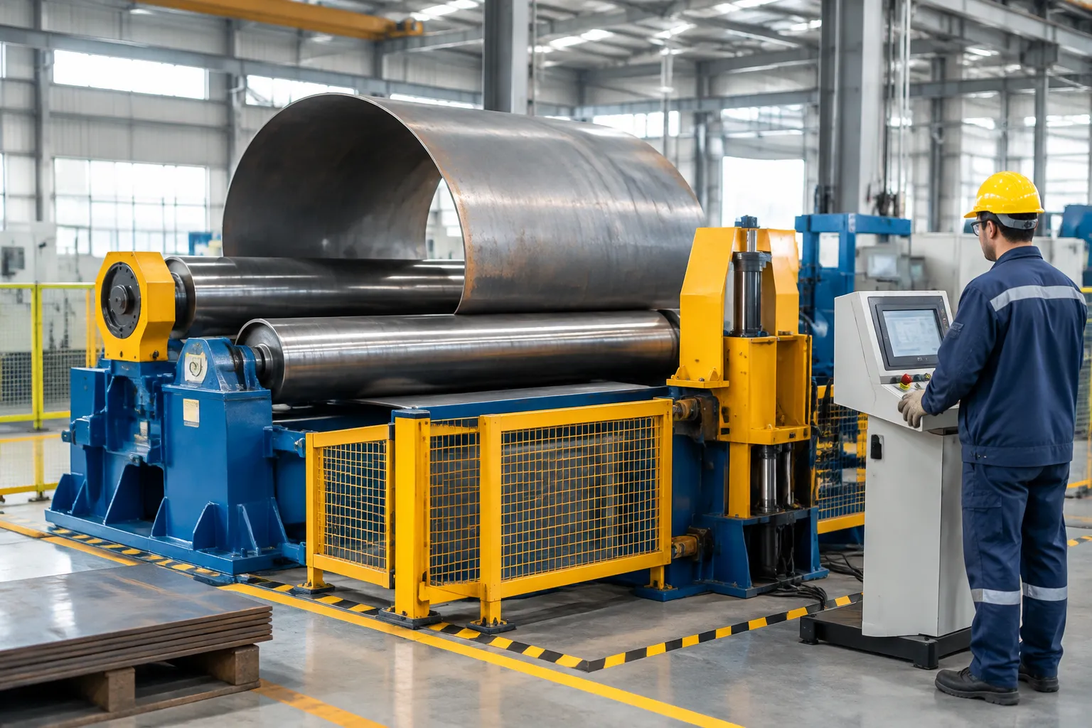
In any heavy-duty metal forming setup, the plate rolling machine working principle relies entirely on how effectively the drive system generates force, manages continuous friction, and synchronizes roll movements. We generally divide these power units into two primary architectures: hydraulic drives and mechanical drive systems.
Hydraulic Drive Architecture and Proportional Valve Synchronization
Modern heavy-plate rolling operations depend predominantly on fluid power. In our hydraulic systems, independent hydraulic cylinders drive the vertical and horizontal movements of the rolls, while hydraulic motors coupled to planetary gearboxes deliver continuous rotational torque.
-
- Proportional Hydraulic Valve Synchronization: High-response proportional valves dynamically adjust oil flow to both cylinder sides. This digital balancing ensures both ends of the roll maintain absolute parallelism within fractions of a millimeter—preventing conical distortion during cylindrical rolling passes.
- Overload Protection: Pressure relief valves automatically limit maximum force to prevent structural frame or roll neck damage when tackling thick-gauge materials.
- Stepless Speed and Pressure Adjustment: Operators can fine-tune roll rotation speed and pinch clamping force independently to match material yield strength and surface condition, especially when handling precision-cut blanks from leveling and cut-to-length lines.
Mechanical Gearbox and Screw Jack Drive Mechanics
Traditional mechanical systems utilize electric motors, heavy-reduction gear trains, and lead screw or worm gear mechanisms to shift rolls and drive rotation.
-
- Direct Mechanical Engagement: Rotational power travels through a multi-stage reduction gearbox directly to the lower roll shafts.
- Screw Jack Positioning: Heavy-duty bronze lead screws position the upper roll downward to exert bending pressure.
- Simplicity and Rigidity: While mechanical systems offer straightforward maintenance and rigid speed control, they lack the dynamic pressure adjustments and rapid overload responses found in hydraulic configurations.
Drive System Comparison: Hydraulic vs. Mechanical
| Parameter | Hydraulic Drive System | Mechanical Gearbox Drive |
|---|---|---|
| Torque Delivery | High continuous torque via planetary reducers | Constant mechanical gear ratio |
| Stroke Precision | High (electronic linear encoders + proportional valves) | Moderate (limited by mechanical backlash and screw wear) |
| Overload Protection | Immediate hydraulic relief valves | Mechanical shear pins or thermal overloads |
| Pre-Bending Power | Exceptional pinch clamping tonnage | Lower clamping force; prone to plate slip on heavy gauges |
| Maintenance Profile | Oil filtration, seal upkeep, valve monitoring | Lubrication of open gears, screw replacement, bearing grease |
Critical Variables Influencing Plate Curvature Precision
1. Yield Strength, Elongation, and Grain Orientation
Material properties directly dictate the required bending force and total elastic recovery:
Yield Strength ($\sigma_s$) and Springback: Higher-strength alloys demand higher normal loads to cross from elastic strain into permanent plastic deformation metal forming. As yield strength increases, material yield strength and springback increase proportionally, requiring tighter bending radii during the pass to hit the target nominal diameter.
Grain Direction: Rolling perpendicular to the plate’s rolling grain reduces cracking risks on tight radii, whereas rolling parallel to the grain requires lower initial force but increases the risk of seam splitting along the outer tension zone.
2. Roll Deflection Mechanics and Structural Crowning
Under heavy bending loads, the top and bottom rolls act as supported beams. The reactive forces cause the center of the rolls to deflect outward, which can produce a barrel-shaped or "canoe" cylinder with loose center dimensions.
-
- Structural Crowning: Rolls are precision-machined with a parabolic diameter increase toward the center. When rolling under full nominal capacity, this built-in curve flattens out to apply perfectly parallel pressure across the entire plate width.
- Dynamic Deflection Management: For high-tonnage forming on our heavy-duty plate rolling machines, pairing static roll deflection and crowning with hydraulic lower-roll backup supports ensures consistent seam alignment across thin and thick plates alike.
3. Conical Plate Rolling Kinematics
Forming cones requires a controlled speed differential between the minor and major diameter edges of the blank:
Side Roll Tilting: The lateral bending rolls tilt independently via hydraulic cylinders, establishing an angled geometry relative to the top roll.
Deceleration Cone Stop: A hardened conical plate rolling attachment contacts the minor radius of the blank. This acts as a pivot stop, slowing the feed rate on the short edge while the larger edge rotates at standard surface speed through our industrial plate rolling machines.
Frequently Asked Questions About Plate Rolling Machines
What is the main working principle of a plate rolling machine?
The fundamental plate rolling machine working principle relies on continuous three-point plastic deformation. A combination of upper, lower, and lateral rolls applies opposed mechanical or hydraulic forces that exceed the material's yield strength. As motorized rolls rotate, surface friction drives the plate through the machine, progressively transforming flat sheet metal into continuous cylindrical, conical, or segmented arc profiles without exceeding the material's ultimate tensile limit.
Why does plate rolling leave flat ends and how do you eliminate them?
Flat ends occur because of the physical distance between the roll contact points. The leading and trailing edges of a plate cannot experience bending moment once they pass outside the tangent line of the active rolls.
The Solution: We eliminate remaining flat ends through an integrated pre-bending phase. By shifting side rolls or lower clamping rolls directly beneath the plate edge, the machine applies localized bending force prior to the full continuous rolling pass.
How does a 4-roll plate bending machine differ from a 3-roll machine in operation?
The primary difference lies in plate handling and clamping control:
3-Roll Machines: Require tilting or offset movement of rolls to pre-bend, and often demand removing and flipping the workpiece to pre-bend both ends on older pyramid models.
4-Roll Systems: Our four-roll plate rolling machines use a dedicated bottom roll to securely pinch the plate against the top roll at all times. Independent side rolls form both the leading and trailing edges in a single continuous setup, eliminating workpiece repositioning and minimizing flat zones.
How do you compensate for roll deflection on heavy thickness plates?
When bending heavy-gauge plate, extreme radial forces cause the center of the rolls to deflect, resulting in an unwanted barrel-shaped cylinder. We manage this through engineered compensation methods:
Roll Crowning: Machining the rolls with a slight convex barrel profile that straightens under full operational load.
Support Rolls: Utilizing dynamic hydraulic support systems beneath the lower rolls on heavy-duty hydraulic plate rolling machines to maintain parallel alignment across the entire working length.
What causes plate slipping during the continuous bending cycle?
Plate slippage happens when the available friction torque between the drive rolls and the workpiece falls below the required bending resistance. Common causes include:
Insufficient Pinch Pressure: Inadequate vertical clamping force between the driving rolls.
Excessive Reduction per Pass: Attempting too aggressive of a radius reduction in a single cycle.
Surface Contamination: Heavy mill scale, excessive lubricants, or polished roll surfaces reducing the coefficient of friction.