
Sheet Metal Machinery Technical Guides & Engineering Resources
Explore practical engineering references for machine selection, process parameters, operation, maintenance, tooling, troubleshooting, and automation across laser cutting, bending, shearing, plate rolling, leveling, and integrated sheet metal production.
Explore Technical Topics
Process Engineering Matrix and Equipment Parameter Optimization
Access comprehensive operational procedures, physical mechanics, and CNC parameter baselines across Haden's eight core metal fabrication machinery platforms, including advanced laser cutting machines. Derived from thousands of hours of empirical shop-floor testing in Haden's global application laboratories, these engineering benchmarks ensure maximum throughput, tight dimensional tolerances, and zero material waste across standard and high-strength alloys.
Fiber Laser Cutting Parameter Optimization
Achieving dross-free kerf geometry and perpendicular edge profiles on high-power sheet metal laser cutting machines requires a calibrated balance among assist gas dynamics, focal position relative to material thickness, and beam delivery power. Nitrogen high-pressure processing creates oxide-free weldable edges on stainless steel and aluminum, whereas ultra-pure oxygen exothermic reactions support thick carbon steel cutting. Specialized multi-stage frequency gradient piercing prevents molten splashback from fouling optical protective windows across both flat sheet equipment and dedicated tube laser cutting machines.
Key Engineering Parameters
- • Assist Gas Pressure: Oxygen at 0.05–0.12 MPa for carbon steel; High-purity Nitrogen at 1.2–2.2 MPa for stainless steel and aluminum alloys.
- • Focal Position Curve: Negative focal offset (-2.0 mm to -6.0 mm) for nitrogen melt cutting; Positive focal offset (+0.5 mm to +3.5 mm) for oxygen combustion cutting.
- • Piercing Strategy: 3-stage pulse-frequency ramp (50 Hz → 250 Hz → 1000 Hz) with dynamic duty-cycle modulation to eliminate blowouts.
- • Nozzle Standoff & Centering: 0.5–1.0 mm working distance with coaxial gas centering tolerance within ±0.03 mm.
High-Power Fiber Laser Parameter Baseline (6 kW – 12 kW)
| Material & Grade | Thickness | Assist Gas / Pressure | Focal Offset | Cutting Speed |
|---|---|---|---|---|
| Carbon Steel (A36 / Q235) | 6.0 mm | O₂ / 0.08 MPa | +1.5 mm | 3.2–3.8 m/min |
| Carbon Steel (A36 / Q235) | 16.0 mm | O₂ / 0.05 MPa | +3.0 mm | 1.2–1.6 m/min |
| Stainless Steel (AISI 304) | 4.0 mm | N₂ / 1.60 MPa | -2.5 mm | 12.0–15.0 m/min |
| Stainless Steel (AISI 316L) | 10.0 mm | N₂ / 2.00 MPa | -5.0 mm | 3.5–4.2 m/min |
| Aluminum Alloy (5052-H32) | 6.0 mm | N₂ / 1.80 MPa | -3.0 mm | 6.5–8.0 m/min |
Preventive Maintenance and High-Precision Calibration Technical Specifications
Execute full lifecycle preventive maintenance and geometric calibration protocols across Haden laser cutting machines and CNC machinery. Standardized service routines preserve sub-millimeter repeat positioning accuracy, eliminate thermal drift, and minimize unscheduled factory downtime.
Daily Operational Pre-Checks
Execute standardized pre-shift verification routines to validate baseline operational parameters, catch microscopic debris buildup, and safeguard electro-hydraulic and optical subsystems prior to full-load production.
- • Laser optics cleaning protocol and protective window inspection: Inspect lower protective window under a high-intensity inspection light for particulate spatter, thermal pinholes, or hydrocarbon film. Clean optic surfaces in a laminar-flow booth using 99.9% spectrophotometric-grade isopropyl alcohol and lint-free optical wipes. Replace immediately if surface pitting exceeds 2% active aperture area.
- • Centralized guide lubrication pressure and oil level checks: Verify automated central lubrication reservoir levels with ISO VG 68 slideway oil. Confirm metered distributor pressure reaches nominal operating threshold (15–25 bar) during automated pump discharge cycles, ensuring continuous boundary lubrication along precision linear guide blocks and ballscrew raceways.
- • Hydraulic circuit operating temperature and leak inspection: Monitor main hydraulic manifold temperature telemetry during cold start and steady-state cycling (maintain within 40–52°C). Scan proportional servo valve blocks, flange couplings, and flexible high-pressure hose crimps for micro-weeping, cavitation acoustic anomalies, or pressure pulse spikes.
Weekly Preventive Maintenance
Conduct secondary mechanical realignment, pneumatic system desiccation, and closed-loop coolant chemistry audits to neutralize progressive environmental wear and maintain continuous process consistency.
- • Laser water chiller deionized circuit conductivity testing: Test dual-circuit cooling water conductivity via calibrated bench meter. Maintain optics circuit conductivity strictly under 2.0 µS/cm and fiber source circuit between 5–10 µS/cm. Flush 25-micron inline mesh strainers and replace ion-exchange resin cartridges if conductivity drift exceeds 15% from base calibration.
- • CNC backgauge multi-axis datum re-zeroing: Command reference homing routines across X1, X2, R, Z1, and Z2 servo axes. Cross-verify mechanical stop contact against absolute optical linear encoders. Recalibrate soft reference limits within the CNC controller to eliminate mechanical hysteresis and thermal drift accumulated across heavy forming shifts.
- • Pneumatic coalescing filter drainage and dewpoint verification: Drain moisture and aerosolized compressor oil from 3-stage filtration banks. Inspect differential pressure indicators across 0.01-micron particulate elements. Verify pressure dewpoint remains at or below -40°C to prevent moisture condensation inside assist-gas proportional valves and pneumatic tool clamps.
Monthly Geometric and Fluid Calibration
Execute comprehensive kinematic alignment verification, hydraulic fluid contamination spectrography, and dynamic clamping torque audits to protect mechanical structural integrity.
- • Hydraulic press brake calibration and linear scale parallelism: Mount digital dial test indicators (0.001 mm resolution) to the moving upper ram. Sweep the entire bed length to measure parallelism against lower table reference datum under no-load and full-load conditions. Clean optical glass scales using anhydrous ethanol and calibrate Y1/Y2 synchronization offset curves.
- • Hydraulic oil particulate contamination sampling and filter element replacement: Draw 100 ml oil samples from the central reservoir sampling port during active circulation. Perform ISO 4406 particle count analysis (target threshold ≤ 16/14/11). Replace 10-micron fiberglass beta-rated return filters and offline continuous conditioning elements when differential pressure delta reaches 1.8 bar.
- • Tool clamping torque audits and punch seat tramming: Audit pneumatic/hydraulic clamping bar retaining bolts and sectional punch wedges using a calibrated ISO 6789 torque wrench. Confirm uniform torque application (±2% tolerance). Inspect lower V-die shoulder grooves and upper tool seating surfaces with precision height gauges to prevent uneven angular forming deviations.
Annual Metrological Overhaul
Deploy factory-grade metrology instrumentation, deep component rebuilds, and electrical thermography to restore machine kinematics to original ISO 230-2 factory tolerances.
- • Multi-axis laser interferometer pitch error compensation: Mount a multi-axis laser interferometer to measure positioning accuracy, linear pitch, yaw, and straightness errors across total axis travel. Generate 3D volumetric compensation matrices and write corrected calibration tables directly to the CNC controller memory, eliminating positioning errors exceeding ±0.015 mm/m.
- • Rotary axis dynamic backlash and preload calibration: Measure rotary chuck axes and heavy-duty planetary gearboxes on advanced tube laser cutting machines using high-resolution optical polygon mirrors and autocollimators. Adjust mechanical preloading or write angular backlash compensation parameters in CNC firmware to maintain angular repeatability within ±0.005°.
- • Hydraulic cylinder seal replacement and proportional valve tuning: Disassemble primary Y1/Y2 hydraulic rams for internal cylinder inspection. Replace dynamic rod packings, chevron seal stacks, and guide rings with OEM Viton elastomer kits. Inspect cylinder walls with internal profilometers (ensuring Ra ≤ 0.15 µm) and re-zero proportional servo valve spool response curves.
- • Electrical cabinet thermographic inspection and contactor refurbishment: Conduct FLIR infrared radiometric imaging across main drive busbars, servo amplifiers, braking resistors, and 3-phase contactor junctions under full motor load. Retorque power terminals exhibiting temperature rises >15°C above ambient, and clean servo drive cooling fans and heat exchangers.
Machinery Maintenance Frequency Reference Table
| Subsystem Category | Component | Inspection Interval | Replacement Interval |
|---|---|---|---|
| Mechanical | Linear guide rails & runner blocks | Weekly visual & lube pressure audit | 20,000 operating hours or dynamic wear limit |
| Mechanical | Recirculating ground ballscrews & preloaded nuts | Monthly axial backlash verification | 25,000 operating hours or >0.02 mm backlash |
| Electrical | AC servo motor encoder feedback cables | Quarterly cable drag chain flex check | 5 years or signal attenuation threshold |
| Electrical | DC bus electrolytic capacitors & contactors | Annually via infrared thermography | 40,000 hours or ESR degradation >20% |
| Hydraulic | High-pressure proportional filter elements (3 µm) | Monthly differential pressure monitor | 2,000 operating hours or 6 calendar months |
| Hydraulic | Y1/Y2 Main cylinder rod seals & wear rings | Semi-annually for external weeping | 8,000 operating hours or 3 years |
| Optical | Cutting head lower protective cover slides | Daily before shift start (micro-inspection) | 1,000 beam-on hours or optical damage |
| Optical | Collimating & focusing fused silica doublet lenses | Monthly thermal focus-shift diagnostic | 10,000 beam-on hours or focal drift >0.3 mm |
Impact of Standardized Maintenance
- ✓ Eliminate up to 65% of unscheduled machine stoppages through early vibration analysis, thermodynamic logging, and fluid particulate detection.
- ✓ Preserve sub-millimeter positioning repeatability (±0.005 mm) across continuous high-tonnage forming and high-acceleration cutting operations.
- ✓ Extend Mean Time Between Failures (MTBF) beyond 25,000 operating hours across critical mechanical, hydraulic, and electro-optical assemblies.
- ✓ Maintain full compliance with ISO 9001 and IATF 16949 quality audits through auditable digital maintenance logs and traceable calibration records.

Haden Integrated Predictive Maintenance
Every system across our lineup of sheet metal laser cutting machines and forming equipment integrates on-board predictive telemetry, thermal gradient compensation sensors, and dynamic lubrication tracking. Our global application engineering team leverages a database of over 100,000 industrial operating hours to continuously optimize component failure signatures and preventive servicing routines.
By pairing systematic preventive maintenance protocols with Haden intelligent real-time CNC compensation algorithms, metal fabricators achieve operational uptime and geometric precision that consistently exceed industry benchmarks—maximizing equipment lifespan and delivering long-term capital investment returns.
Need a Machinery Maintenance Checklist?
Use a structured maintenance reference to organize routine inspection, lubrication, cleaning, calibration, tooling checks, and service records for sheet metal machinery.
Maintenance requirements should be adapted to the specific machine model, operating conditions, and manufacturer service instructions.
Press Brake Tooling Selection, Laser Optics Calibration & Shear Blade Management
Optimize sheet metal fabrication yield, eliminate cut edge burrs, and protect press frame rigidity. Haden engineers hardened bending tool systems, vacuum-degassed shear knives, and optical consumables for tight dimensional tolerances and extended production runs across industrial laser cutting machines.
Laser Cutting Nozzles & Protective Windows
Employ single-layer nozzles (1.0–2.0 mm) with high-pressure nitrogen or compressed air to process stainless steel and aluminum on sheet metal laser cutting machines. Use double-layer nozzles (1.4–3.0 mm) with internal diffusers for low-pressure oxygen cutting of carbon steel to suppress boundary vortexing.
Swap lower protective windows when optical transmittance drops >0.5% or focal drift exceeds 0.8 mm on high-speed tube laser cutting machines. Thermal blooming caused by spatter contamination accelerates beam divergence and bottom-edge dross formation.
Perform adhesive tape pulse shots every 8 operating hours. Adjust the cutting head X-Y centering screws until the beam burn center remains concentric within ±0.05 mm of the nozzle orifice.
Press Brake Tooling Selection & V-Dies
Apply V = 6 to 8t for standard carbon steel sheet under 450 MPa tensile strength. Mandate V = 10 to 12t for high-strength steel (Hardox, Weldox) to prevent shoulder galling and micro-cracking.
Haden deep CNC laser hardening creates an HRC 58–62 surface wear zone down to a 3.5 mm depth, retaining a ductile 42CrMo4 core that absorbs peak shock loads without risk of brittle shank breakage.
Verify sectional punch-and-die alignment within ±0.01 mm/m. Synchronize CNC mechanical crowning wedges with material yield strength to ensure uniform bend angles across the full bed length.
Shearing Blade Gap & Forming Rolls
Precision rectangular shear blades forged in D2 and Cr12MoV provide 4 ground cutting edges. Rotate edges systematically at 40,000 to 60,000 stroke intervals to maximize blade longevity and reduce tooling costs.
Calibrate blade clearance to 6–8% of material thickness for mild steel, and 10–12% for stainless grades. Improper gap clearances cause sheet twisting, excessive rollover burrs, or hydraulic overpressure.
Industrial hard chrome plating on 3-roll and 4-roll machines (0.05–0.08 mm thickness, >65 HRC) prevents abrasive mill scale pick-up and stops carbon cross-contamination on polished stainless plates.
Consumable Wear Life, Inspection Cycles & Service Criteria
| Tooling / Consumable Class | Base Substrate | Target Processing Material | Inspection Frequency | Expected Service Life | Mandatory Maintenance Action |
|---|---|---|---|---|---|
| Fiber Laser Cutting Nozzles | High-Conductivity Tellurium Copper | Carbon Steel / Stainless / Aluminum | Every 8 Cutting Hours | 120–180 Arc Hours | Clean spatter with a brass brush; check orifice roundness and coaxial alignment. |
| Laser Protective Windows | Corning 7980 Fused Silica Quartz | Reflective Alloys / Heavy Carbon Plates | Every Shift (Microscope Check) | 200–350 Beam Hours | Replace upon any micro-spatter pits, thermal burns, or coating degradation. |
| CNC Press Brake Punches & V-Dies | 42CrMo4 Laser Hardened (58–62 HRC) | Structural Mild & High-Tensile Steel | 50,000 Bending Strokes | 500,000+ Cycles | Verify tip radius wear with optical radius gauges; stone away minor shoulder burrs. |
| Hydraulic Shear Blades | Vacuum Heat-Treated Cr12MoV / D2 | Sheet & Heavy Plate up to 25 mm | 15,000 Shear Cycles | 160,000 Cuts (4 Edges) | Rotate to the next sharp 90° edge; recalibrate blade gap clearance with feeler gauges. |
| Plate Bending Machine Rolls | Forged 42CrMo + Hard Chrome Plating | Stainless Clad & Pressure Vessel Plates | 200 Operating Hours | 3–5 Production Years | Inspect roll crowning profile; clean and polish away abrasive mill scale build-up. |
Custom Tooling Alloys Built for Demanding Forming Cycles
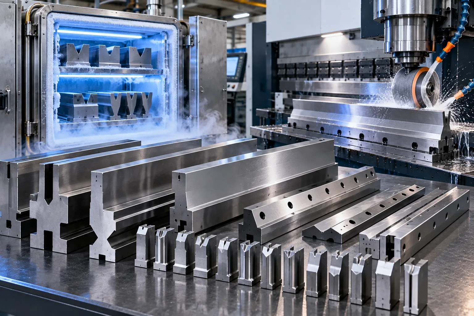
Every standard and custom tooling package from Haden undergoes cryogenic deep-freeze stabilization and CNC profile grinding, ensuring uniform load distribution across high-tonnage multi-stage bending and heavy plate shearing.
Air Bending Tonnage & V-Die Evaluator
Estimate press brake bending force based on material tensile strength, sheet thickness, bend length, and V-die opening.
This calculator provides a preliminary air-bending force estimate. Actual press brake selection should also consider tooling capacity, bend geometry, material condition, grain direction, required radius, machine working length, off-center loading, and manufacturer tonnage limits.
Need application-specific tooling, bend-radius, tonnage, or press brake configuration guidance?
Sheet Metal Defect Troubleshooting Guide
Diagnose common cutting, bending, shearing, rolling, and V-grooving defects by separating machine condition, process parameters, material behavior, and tooling variables before corrective adjustments are made.
Three-Step Diagnostic Workflow
Establish the machine baseline first, isolate one process variable at a time, and verify the result with appropriate measurement equipment.
Verify Machine Condition
Confirm mechanical datums, tooling alignment, nozzle concentricity, hydraulic condition, clamping, guides, sensors, and relevant machine calibration before changing CNC process values.
Adjust One Variable
Change one parameter per test cycle while holding other variables constant. This helps separate gas, focus, speed, crowning, tooling, blade-clearance, and material effects.
Measure & Confirm
Inspect the resulting part with suitable dimensional, angular, profile, surface, or CMM measurement methods and compare the result with the drawing requirement.
Root Cause Diagnosis & Corrective Actions
Re-solidified material remains along the lower cut edge, accompanied by rough striation patterns, slag beads, or increased secondary deburring.
- • Assist-gas delivery and gas quality
- • Nozzle condition and beam concentricity
- • Focal position relative to plate thickness
- • Cutting speed and pierce/cut parameters
- • Verify nozzle centering and nozzle condition.
- • Confirm gas pressure against the approved cutting table.
- • Test focal-position changes in controlled increments.
- • Adjust feed speed while keeping other variables constant.
Try another symptom, machine type, or process keyword.
Verify the Baseline Before Changing the Process
Exact tolerances and adjustment limits depend on machine model, tooling, material grade, thickness, controller configuration, and the required part specification.
Still Troubleshooting a Recurring Production Defect?
Share the machine type, material, thickness, process parameters, defect photos, and part requirements. Haden application engineers can review the application and help identify the next diagnostic steps.
Automation Integration and Industrial Control Protocols
Scale from standalone CNC machinery to fully synchronized, lights-out fabrication cells. Haden delivers unified hardware and software architecture, linking industrial laser cutting machines, robotic bending, grooving, and material handling systems into intelligent production lines.
Digital Bus & CAM Simulation
CAM Offline Programming & Bending Simulation
Minimize shop-floor setup time with 3D kinematic sequencing, virtual collision checking, and automated nesting optimization.
- 3D bending collision detection with multi-station tooling clearance validation.
- Automated common-line cutting path generation with dynamic micro-joint placement.
- High-yield remnant-sheet nesting algorithms configured for mixed-thickness runs.
Industrial Bus Interoperability & CNC Industrial Control
Standardized real-time communication protocols connect machine-level PLCs directly to plant-wide MES and ERP networks.
Continuous telemetry monitoring provides real-time OEE tracking, cycle counting, and predictive maintenance alerts.
Robotics & Material Logistics
Robotic Bending Follower Cell Kinematics
Precision robotic bending cell programming dynamically tracks panel deflection angles in sync with press brake beam movement.
- Six-axis industrial robot trajectory synchronized to CNC press brake Y1/Y2 ram velocity.
- Automated gripper regripping sequences engineered to prevent sheet deflection and backgauge load.
- Dual-channel optical safety muting curtains supporting continuous, high-speed bending runs.
AS/RS Interfacing & High-Bay Storage
Automated high-bay material storage systems feed sheet stock directly to automated sheet metal laser cutting machines and shearing centers on demand.
- Automated cassette pallet shuttle with ultrasonic sheet double-feed detection sensors.
- Pneumatic air-knife fanning and magnetic sheet fanners for reliable separation of oiled raw sheets.
Turnkey Digital Fabrication Lines Engineered for Scale
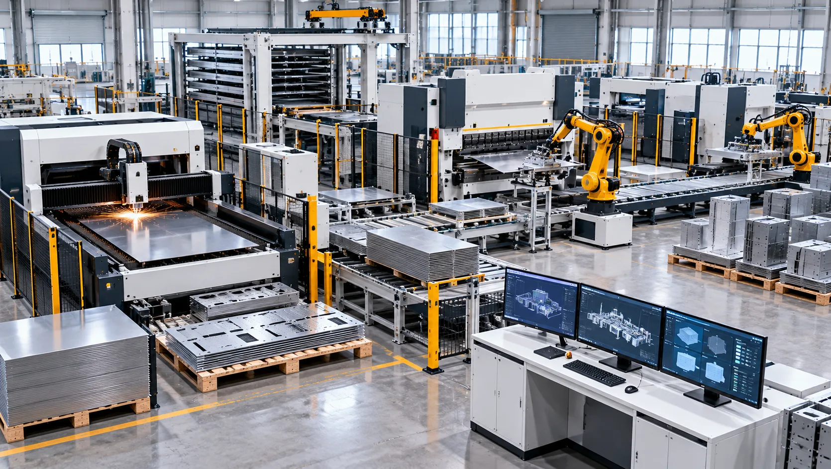
Haden automation engineers configure modular manufacturing lines, connecting advanced sheet and tube laser cutting machines, high-speed grooving stations, and robotic bending cells under unified supervisor software.
Workshop Safety Protocols and International CE Compliance Standards
Heavy-gauge industrial sheet metal fabrication requires rigorous alignment between multi-ton hydraulic pressures, high-power optical radiation, and uncompromising plant floor safety engineering. Modern high-speed machine tools must adhere to strict international fabrication safety directives governing functional circuit architectures, dynamic optical interception zones, redundant hydraulic valves, and combustible particulate mitigation. Establishing verifiable safety measures protects machine operators, prevents costly regulatory shutdowns, and ensures immediate readiness for third-party CE and OSHA compliance audits.
Haden designs and builds precision sheet metal machinery in strict compliance with harmonized European Standards (EN/ISO) and North American safety codes (ANSI/NFPA). This engineering technical guide defines the essential safety protocols across Class 4 industrial laser-cutting-machines, press brake dynamic optical safeguarding systems, fail-safe hydraulic circuits, and environmental health specifications for modern metal fabrication plants.
Subsystem Safety Standards & Operational Risk Controls
Class 4 Laser Radiation Containment
High-power cutting heads used on modern sheet-metal-laser-cutting-machines emit coherent near-infrared radiation at 1064 nm wavelengths. Direct beam exposure or diffuse reflections cause instantaneous retinal burns and serious thermal injuries.
- OD6+ certified safety viewing windows tested to EN 207 and EN 60825-1 optical density criteria.
- Dual-channel electrical interlock circuits on access panels triggering active beam shutdown under 20 ms.
- Negative pressure cutting housing preventing hazardous aerosol and fume escape into ambient shop air.
- ATEX-compliant extraction systems preventing combustible aluminum and carbon dust deflagration.
Press Brake Optical Guarding Systems
Hydraulic and servo press brakes produce severe pinch-point hazards at the upper punch and lower die interface during high-speed downstroke approach and final workpiece bottoming.
- Dynamic optical light barriers (DSP / AKAS) tracking synchronously with the moving upper beam.
- Auto-calibrated mute point transitions allowing rapid approach down to 2 mm above the workpiece.
- EN 12622 dual-channel foot switches and anti-tie-down dual-hand controls with monitored relays.
- Rear perimeter physical safety barriers interlocked with multi-axis backgauge servo drives.
Hydraulic & Mechanical Failsafe Controls
High-tonnage hydraulic shears, plate rolling machines, and forming presses store massive potential energy. System hardware must prevent accidental ram drop in the event of power or component failure.
- Dual monitored safety cartridge valves providing independent cross-checked hydraulic redundancy.
- Mechanical ram-locking safety drop pins for positive mechanical retention during die changes.
- Direct-flanged counterbalance check valves arresting cylinder descent upon line pressure loss.
- Integrated overpressure relief modules preventing frame overloading and structural fatigue.
Plant Environmental Safety & Ergonomics
Modern workshop EHS mandates comprehensive control over toxic thermal cutting emissions, high sound pressure levels, and musculoskeletal strain during manual and automated sheet handling.
- Sectional pneumatic extraction tables achieving surface capture air velocities above 0.5 m/s.
- Acoustic sound dampening panels dampening continuous machine noise below 78 dBA at 1 meter.
- Elastomer vibration isolation mounts dampening dynamic shockwaves from guillotine shear blades.
- CNC sheet support followers and ball transfer tables reducing operator repetitive load strain.

Haden Multi-Tier Redundancy & Safety PLC Integration
Machine tool safety is an integrated element of the baseline mechanical, hydraulic, and electrical layout. Haden fabrication machinery features dedicated Safety Programmable Logic Controllers (Safety PLCs) and fail-safe fieldbus networks to govern emergency stops, light curtain muting algorithms, dynamic servo braking, and hydraulic valve spool position monitoring.
All high-risk circuits achieve Performance Level d or e (PL d / PL e) under ISO 13849-1 with Category 4 hardware architecture. In the event of a single component malfunction—such as a welded contactor, broken light curtain sensor cable, or stuck valve spool—the safety controller identifies the fault immediately before the next operational stroke, bringing the machine to an instant, de-energized safe stop.
Regulatory Compliance Standards & Safety Performance Levels
The matrix below illustrates the direct engineering alignment between international directives, safety integrity benchmarks, and Haden sheet metal equipment specifications across heavy forming lines, roll benders, and precision tube-laser-cutting-machines.
| Machinery Subsystem | Harmonized Standard | Required Safety Level | Primary Protection Mechanism | Audit Compliance Criteria |
|---|---|---|---|---|
| Fiber Laser Cutting Systems | EN ISO 11553-1 / EN 60825-1 | PL e / Cat 4 | Enclosed Class 4 cabin with OD6+ interlocked filter viewing windows | Zero measurable optical radiation leakage along perimeter seams |
| CNC Hydraulic Press Brakes | EN 12622 / ANSI B11.3 | PL e / Cat 4 | Dynamic optical guards with auto-muting and monitored dual hydraulic valves | Validated stopping time performance and certified overrun distance tests |
| Hydraulic Guillotine Shears | EN ISO 13984 / ANSI B11.4 | PL d / Cat 3 | Front finger-guard grille and rear multi-beam optical intrusion curtains | Hydraulic hold-down pinch zone physical envelope verification |
| Plate Bending & Rollers | ISO 12100 / OSHA 1910.212 | PL d / Cat 3 | Full-perimeter emergency trip wire with interlocked drop-end safety latch | Instantaneous roll rotation brake activation upon circuit interruption |
| CNC Sheet Metal V-Groovers | ISO 13849-1 / EN 60204-1 | PL d / Cat 3 | Synchronized pneumatic clamp interlocks with protective chip deflector guards | Automated gantry zone entry lockout during rapid traverse cycles |
| Automated Robotic Cells | ISO 10218-2 / ANSI/RIA R15.06 | PL e / Cat 4 | Fenced safety cells with trapped-key interlocks and multi-zone laser scanners | Synchronized robot-press brake safe speed and separation monitoring |
Plant EHS Safety Audit & Inspection Guidelines
Sheet metal fabrication facilities should implement standardized periodic inspections to preserve machine safety integrity, satisfy regulatory audits, and ensure zero-incident operations.
Daily Shift Inspections
- Verify optical light curtain alignment and perform functional trip tests using standardized test pieces.
- Check laser enclosure door interlock switches to verify active beam shutoff response.
- Inspect hydraulic system operating pressure, oil temperature, and valve seal integrity.
- Ensure protective laser viewing windows are clean and free of micro-cracks or pitting.
Monthly Functional Audits
- Test emergency stop circuit cycle times and verify manual safety relay reset logic.
- Inspect mechanical ram safety drop pins and check cylinder counterbalance valve holding force.
- Measure dust extraction face airflow velocity and inspect spark arrestor filter modules.
- Perform grounding continuity tests across electrical control enclosures and machine frames.
Annual Certification Audits
- Execute comprehensive press brake stopping distance and ram overrun metrology calibrations.
- Conduct third-party optical containment and laser power density radiation leakage inspections.
- Replace certified high-pressure hydraulic flex lines in accordance with fatigue life schedules.
- Review operator safety training records and verify factory Lockout/Tagout (LOTO) protocols.
Turn Your Part Requirements Into the Right Machine Configuration
Share your drawings, material, thickness, part dimensions, production volume, and process requirements. Haden application engineers can review the project and help evaluate machine configuration, tooling, process capability, and automation options.
Based on actual part and process requirements
Machine, tooling and process considerations
From standalone equipment to automation
Start With Your Application
The more application data you provide, the more accurately the equipment configuration can be evaluated.
Part Drawings & Geometry
DXF, DWG, STEP, PDF, or representative part drawings for process and machine evaluation.
Material & Thickness
Material grade, thickness range, tube or sheet profile, and other relevant workpiece information.
Production Requirements
Part dimensions, production volume, tolerance targets, cycle requirements, and product mix.
Automation Requirements
Loading, unloading, storage, robotic handling, bending, or production-line integration requirements.